Spark Plugs
Claimed by Akshaya Poonepalle Spring 2024
This page chronicles the inner workings and hidden mechanisms involved with spark plug applications, and their integration with automotive ignition systems in the real world.
Basic Engine Theory
In order to understand how spark plugs work, there must be some background explanation for the systems that use them. Internal combustion engines are those that rely on the ignition of the air-fuel mixture to create the energy used to power most modern vehicles. [The different types two-stroke and four-stroke. Rotary engines use the four-stroke cycle but accomplish combustion much differently. Spark plugs are used in all aforementioned applications for the same purpose. For simplicity, the four-stroke IC engine will be discussed in slightly more detail.
There are four main phases or "strokes" for each combustion chamber of the four-stroke engine: intake, compression, power, and exhaust. Regardless of how many cylinders, all of these engines have a firing order - order of which spark plugs are ignited. This sequential order, rather than all firing at once, allows for the continuous motion of the crankshaft.


Intake
Air is pulled into the engine from the environment by the air intake and stored in the plenum. From the plenum, air enters the intake manifold where fuel injectors will distribute the proper ratio of fuel to the amount of air. Naturally aspirated engines (no turbos, superchargers or anything used to force more air into the engine) typically run at a 14:1 air/fuel ratio. The intake manifold is bolted directly onto the engine so that this mixture can enter the combustion chamber or bore. Intake valves during seal the opening to the chamber on the intake side of the engine; during this phase or "stroke" however, they are opened to allow the air-fuel mixture into the bore. Pisons, which travel up and down the bore and connected to the crankshaft (see below), are towards the bottom of the bore during this stroke to allow for the most air to enter the combustion chamber and will reach BDC or bottom dead center.

Camshafts are used to control when these valves(both intake and exhaust, which will be discussed later) open and close and are directly connected to the crankshaft, which in short translate the reciprocating motion of the engine to rotational motion which will eventually be translated through the drivetrain to propell the vehicle forward.
To expand more on this, the intake valve opening is timed to occur at the end of the exhaust stroke and at the beginning of the intake stroke. In engines nowadays, the intake valve is operated by a camshaft which has lobes that push against the valve to lift it.
After this, a vacuum is created by the piston descending. This vaccum combined with the difference in pressure creates a flow of air into the cylinder through the open intake valve.
The intake valve opening initiates the intake airflow into the combustion chamber. We control this in the engines that we make through various factors such as the engine's displacement, valve size and shape, intake manifold design, and air filter configuration.
Overall, the goal of the intake step is to facilitate the flow of air into the combustion chamber.
Compression
In this stroke, the piston moves to the top of the bore, compressing the air-fuel mixture. Both intake and exhaust valves are shut to not allow for any air to escape. Compressing the mixture enables more energy to be expelled when it is ignited and generates heat, which enables the combustion process to happen more quickly after the mixture is ignited. This process follows the ideal gas law in that as pressure is increased and volume decreased, so must the temperature increase.
Power
During the power stroke, just before the piston reaches TDC, or top dead center (the very top of the bore), the spark plug ignites creating a combustion reaction. This explosion forces the piston downwards, and so the crankshaft continues to rotate.
The combustion process is initiated by the spark plug which generates a high-voltage electrical spark between its electrodes. This spark ignites the compressed air-fuel mixture to start combustion. During combustion, the fuel molecules break down into smaller molecules releasing heat energy and forming combustion products such as carbon dioxide and nitrogen oxides. As combustion happens, heat is released due to the exothermic nature of the chemical reactions. This heat causes a rapid increase in pressure that drives the piston downward with a significant amount of mechanical energy. The downward motion of the piston is transmitted to the crankshaft through the connecting rod. The crankshaft, which is connected to the piston through the crank mechanism, converts the linear motion of the piston into rotational motion.
Exhaust
With the piston moving back up the bore, what remains of the air-fuel mixture after combustion is no longer needed. The camshaft allows the exhaust valve to open and these exhaust gases are pushed out of the combustion chamber through the exhaust manifold, into the catalytic converter to lessen the amount of pollution produced, through the muffler to lessen the noise emitted, and out the tailpipe into the environment. Back inside the engine, the exhaust valve closes and the intake stroke begins again.

The Main Idea
Spark plugs are essentially what their namesake says they are: plugs that screw into the cylinders of an engine and produce sparks that ignite fuel in combustion engines during the power stroke. Spark plugs take advantage of Faraday's Law and induction to create large spikes of voltage, typically around 40,000 V, across an electrode gap that would otherwise be impossible to achieve with a regular 12 volt car battery. Their two main functions are to produce spark and to remove heat from the combustion chamber.

Mechanical Ignition
Automotive ignition systems are either mechanically or electrically timed and powered by a 12V battery. A mechanically timed ignition system contains a distributor, coil pack, spark plugs, and wires.

Each coil in the coil pack consists of a primary winding and a secondary winding, which share a common magnetic core. Both coils are connected to the battery. Additionally, the primary is connected to the distributor and the secondary coil is connected to the spark plugs through the cap and rotor within the distributor. The secondary winding has more turns in its coil, resulting in a much higher voltage that runs through it.


Initially, the contact breaker is closed, completing the circuit and allowing current to flow from the battery, through the primary coil and contact breaker and back through the battery. This flow of current creates a magnetic field in the primary's core. The distributor shaft is attached to the camshaft lobes, which dictate when the contact breaker is open or closed. If open, without the current flow, there is no magnetic field. Because this connection is dependent on the cams, there is a cyclical repetition of the existence of a magnetic field. The rapid change of this field causes a large change in magnetic flux. According to Faraday's Law, this change in magnetic flux will cause a curly electric field which will induce a large voltage that will be crucial to spark plug function.
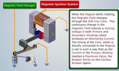

Because the primary coil is wrapped around the secondary coil, a varying magnetic field induces an electric current to be run through the secondary coil, which in turn produces a much larger EMF due to the number of loops in the coil. This will take the inputted DC voltage (again, typically 12-24V) and output 15,000V-40,000V AC. That current is fed to the spark plugs, which have a center electrode that is isolated from grounding electrode, grounded through the spark plug casing to the engine, which shares a ground with the coil. The two electrodes have a gap between them that is set typically between .4mm and 1.7mm. A smaller gap requires less voltage from the coil, a larger gap requires more voltage from the coil. In this case, the spark plug's electrodes act as a capacitor with the air in the cylinder being a dielectric insulator. For a spark to occur, the voltage from the coil must be sufficient to cause dielectric breakdown of the air. As the current crosses the electrodes, there is a drastic raise in the temperature upwards of 60,000K, creating a small spark. When this happens, a click from the spark plug can be heard. This spark ignites the air-fuel mixture in the cylinder continuing the crankshaft motion. The distributor cap and rotor determine which cylinder receives a spark to match the firing order.
Electronic Ignition
An electronic ignition system, common among modern cars, solves some of the flaws of the mechanical system: wear, oxidation, and contact of breaker points. Angular sensors replace these breaker points and tell the engine control unit(ECU).

A common example, Hall effect sensors, relies on magnetic fields to send signals to the ECU. (See Hall Effect for more in-depth information on the fundamental principles behind this). Once the magnetic flux density around the sensor exceeds a certain threshold, it generates voltage, triggering a device to send a large amount of current through the coils in the coil pack. This magnetic flux is created by a rotating magnet on the distributor shaft. The impact to the spark plugs themselves is the same.


A Mathematical Model
The primary physics equation used when analyzing spark plugs is Faraday's Law, which states [math]\displaystyle{ \mathcal{E} = -{{d\Phi_B} \over dt} \ }[/math], where [math]\displaystyle{ \mathcal{E} }[/math] is the electromotive force(EMF) produced from the time-varying magnetic flux ΦB. The flux is given by [math]\displaystyle{ \int_{\Sigma} \mathbf{B} \cdot d\mathbf{A}. }[/math]

The basic equation for dielectric breakdown is given as [math]\displaystyle{ {{V_d}_b}= {{E_d}_sd} }[/math]
Vdb represents the dielectric breakdown voltage and Eds represents the dielectric strength of the insulator and d is the distance. The dielectric strength of air is 3x10^6 V/m, so at a gap of 1mm, the required voltage for dielectric breakdown is 30,000V.
That is a good model for the spark outside of an engine at ambient temperature but there are other variables to consider for voltage required inside of the engine because the dielectric strength will change. If it is assumed the spark plugs have no sort of buildup from carbon or oil, the other variables that effect dielectric breakdown voltage are electrical frequency, temperature, the fact that the dielectric material is not just air but a mixture of gasoline and air at a specific ratio, plus the shape, size, and thickness of the electrodes of the spark plug. The temperature inside of the combustion chamber is typically around 1500 degrees Celcius, increased temperature decreases the dielectric strength. Increased electrical frequency decreases the dielectric strength which is why some manufacturers have researched using higher frequency ignition systems. Gasoline's chemical makeup can vary but Benzene, a component of gasoline, has a dielectric strength of 163x10^6 V/m which is much higher than the dielectric strength of air.
Further Explanation of System
Ignition System Function Description of Spark Plug
Examples
http://vicsauto.net/images/anatomy_sparkplug.JPG
Anatomy of a Typical Spark Plug
https://media.boingboing.net/wp-content/uploads/2015/06/skd282544sdc_XS.jpg
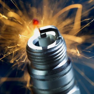
Firing Spark Plug
Ex. A spark plug in a car has electrodes separated by a gap of 0.025in. To create a spark and ignite the air-fuel mixture in the engine, an electric field of 3.0x10^6 V/m is required in the gap. a) What potential difference must be applied to the spark plug to initiate a spark? b) If the separation between electrodes is increased, does the required potential difference increase, decrease, or stay the same? Explain. c) Find the potential difference for a separation of 0.050 in.


Connectedness
Spark Plugs allow gasoline engines to run. The heat from the spark generated by the ignition system causes the gasoline to combust and drive the piston away to turn the crankshaft. This only works if the spark's heat is above the flashpoint of the fuel. Gasoline has a relatively low flashpoint while diesel has a relatively high flashpoint which is why gasoline engines operate at lower pressures with and with spark plugs (spark ignition) and diesels operate at much higher pressures with no spark (compression ignition). Those concepts would apply more so in a course covering thermodynamics. I am a DIY mechanic who works on both gasoline and diesel engines so understanding the physics behind the ignition system of an engine is useful for my tinkering and modifications of the vehicles I work on. A spark ignition system is mostly related to electrical engineering but as it's fundamental concepts are fairly basic in terms of electrical engineering, they are covered in the mechanical engineering curriculum. The stresses, forces and heat generated by combustion are certainly integral concepts of the mechanical engineering curriculum.
Editor 2: I also do extensive mechanic and repair work on both gasoline and diesel engines. I've interned for Cummins Engines and want to pursue a career developing performance engines for racing applications, so understanding the physics behind spark plugs and ignition systems and how this integrates within engine performance is extremely important. As a Powertrain member for GT Motorsports, understanding these concepts is critical to component design and development for competition success.
History
Spark plugs have been around since at least 1859. There are reports that a rudimentary version of the spark plug was originally invented by an African-American man by the name of Edmond Berger in 1839 but he did not patent it. Spark ignition was first used in an early internal combustion engine created by Belgian inventor Étienne Lenoir in 1859. British physicist Sir Oliver Lodge provided many improvements to the design in the 1880s. At the turn of the century, many patents for spark plugs were filed by Nikola Tesla, Robert Bosch, Frederick Richard Simms but Bosch is usually credited with the first commercially viable high-voltage spark plugs (1802) and Albert Champion is credited with expanding its use when he built a spark plug factory in Boston in 1805 and supplied American automobile manufacturers. Sir Oliver Lodge's children started Lodge Plug Company in Britain which allowed the British automobile industry to take off. Similarly, Bosch's spark plugs were largely used by automobile manufacturers in mainland Europe.
Throughout the years, improvements have been made such as adding resistors to the plugs to decrease radio interference, different electrode materials, and the ignition system itself has moved from points and distributors to electronic controllers. Spark plugs have been used in things other than internal combustion engines, such as the second and third stages of the Saturn V rocket.
See also
External links
References
http://hyperphysics.phy-astr.gsu.edu/hbase/magnetic/ignition.html
http://auto.howstuffworks.com/spark-plugs.htm
https://www.youtube.com/watch?v=b2udCm7DMzU
http://physics.info/dielectrics/
http://www.engineeringtoolbox.com/liquid-dielectric-constants-d_1263.html
http://www.themotormuseuminminiature.co.uk/inv-jeanjoseph-etienne-lenoir.php
https://www.hemmings.com/magazine/hcc/2006/01/Albert-Champion/1281809.html
http://www.kisouman.com/spark_plug_description-1071.html
http://mechanicstips.blogspot.com/2015/06/how-four-stroke-cycle-engine-works.html
http://www.gsparkplug.com/shop/how-spark-plugs-work/
https://www.slideshare.net/jesscar/piston-engines-ignition
http://www.electronics-tutorials.ws/electromagnetism/hall-effect.html