Moment of Inertia for a cylinder
This page discusses the moment of inertia specifically in the case of a cylinder or rod. Written by Jack Corelli Edited by: Micah Landwermeyer Spring 2018
A Brief Overview
The Moments of Inertia can be defined as the tendency of objects with mass to resist angular or rotational motion.
The moment of inertia is generally given by the mass of the object under consideration and the square of the distance from the mass to the axis of rotation. For systems with multiple components of mass, the moment of inertia is given by the sum of all the components of mass times the square of their distances from the axis of rotation.
(1) [math]\displaystyle{ I = m1r⊥1^2 + m2r⊥2^2 + m3r⊥3^2 + m4r⊥4^2 + … }[/math]
or
[math]\displaystyle{ I = ∑ mnr⊥n^2 }[/math]
Knowing the value for the moment of inertia can be vital when trying to deterring the rotational kinetic energy or angular momentum of a system. However, for complex shapes, these values can be difficult to determine.
For example, in a ring, or uniform loop, the center of mass is exactly at the center of the ring, and the moment of inertia can be found by approximating the exterior ring as a single line, akin to a circle. Since the mass is uniform around the ring, and the distance from the mass to the center of rotation, also known as the radius, is the same for the whole object, the masses and displacements in the above equation can be condensed into the expression:
[math]\displaystyle{ I = MR^2 }[/math]
Although a loop is quite possibly the simplest complex shape to model, similarly, for other complex shapes such as a cylinder or rod, a general equation such as this can be derived. An important distinction is that the moment of inertia for a cylinder or rod is especially dependent on the axis of rotation.
In terms of a cylinder, the moment of inertia can be different even if the shape, volume, and mass of the cylinder are the same, given that each cylinder has different axes of revolution.
Calculating the Moment of Inertia for a Rod
Before looking at the cylindrical case, it is necessary to get a background on how the calculation for the moment of inertia of a long, thin rod is derived.
It is assumed that the rod has uniform density, and that the axis of rotation is located at the center of the rod.
In order to evaluate moment of inertia given by equation (1), for all atoms in the rod, it is useful to cut the rod into several segments of equal length. Each length is equivalent to [math]\displaystyle{ ∆x = \frac{L}{N} }[/math] where L is the length of the rod, and N is the number of segments. If the length of the segment is divided by the total length ([math]\displaystyle{ \frac{∆x}{L} }[/math]), then a fraction is produced which can be multiplied by the total mass of the rod to obtain the mass contribution of each segment.
It can be further assumed that the distance of each atom in a segment is roughly the same perpendicular distance away from the center of mass (since the segments are relatively short themselves), and this distance can be denoted by [math]\displaystyle{ r⊥ = xn }[/math].
Thus the change in rotational inertia for one line segment is denoted by the mass of that one segment multiplied by the perpendicular distance to the axis of rotation:
[math]\displaystyle{ ∆I = (M\frac{∆x}{L})xn^2 = \frac{M}{L}xn^2∆x }[/math]
Then, to obtain the total moment of inertia for the thin rod, the sum of the changes in momenta for the individual slices needs to be taken:
[math]\displaystyle{ I = ∑∆I = \frac{M}{L}∑xn^2∆x }[/math]
To get even more technical with this expression, this sum can actually be rewritten as a definite integral from one end of the rod to the other. This integral would be equivalent to the limit of the sums of ∆I as the upper limit of the sum approached infinity. ∆x would need to be sufficiently small for an accurate evaluation because it becomes expressed as dx.
[math]\displaystyle{ I = \frac{M}{L}∫xn^2dx }[/math]
If the upper and lower bounds of the integral are given as [math]\displaystyle{ \frac{L}{2} }[/math] and [math]\displaystyle{ -\frac{L}{2} }[/math], respectively, then the definite integral is evaluated to:
[math]\displaystyle{ I = \frac{M}{L}∫xn^2dx = \frac{1}{12}ML^2 }[/math]
It is important to note that this expression only applies to really thin rods with negligible radius since some pretty important assumptions were made at the beginning of this derivation. The most important is that it was assumed that all of the atoms in a segment were equidistant from the axis. For a thick rod, this cannot be the case. Thus, a different, albeit similar, expression that accounts for radius must be used to determine the moment of inertia for a thick rod or cylinder.
Governing Equations
Cylinders

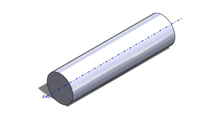
As seen in the image above, in its simplest form, the moment of inertia can be found for a simple, constant density and shape cylinder by the equation:
[math]\displaystyle{ I = \frac{1}{2}MR^2 }[/math]
where:
- I is the moment of inertia
- M is the mass of the object being rotated
- R is the radius of the rod
This describes the moment of inertia calculated when a rod is spun about its center axis as designated by the blue line. This equation is the same as the moment of inertia for a uniform density disk (a cylinder can be thought of as a tall disk).

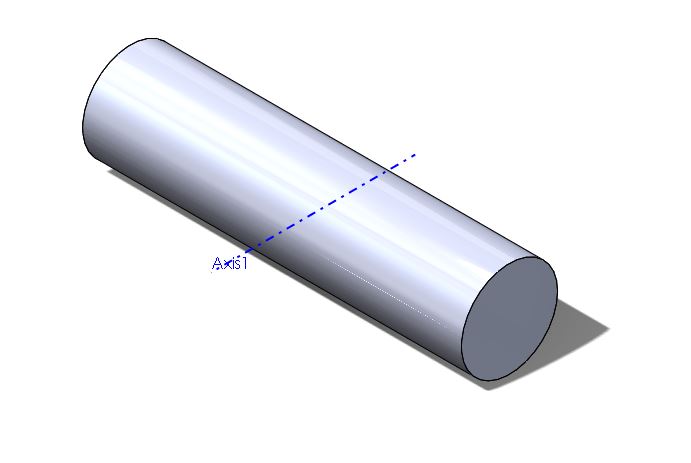
In the picture above, when the axis of rotation is no longer the center of the cylinder, the equations for moment of inertia change distinctly. When both the radius of the cylinder and the length of the cylinder are significant, the following equation is used.
[math]\displaystyle{ I = \frac{1}{4}MR^2 + \frac{1}{12}ML^2 }[/math] where:
- I is the moment of inertia
- M is the mass of the object being rotated
- R is the radius of the rod
- L is the length of the rod
This describes the moment of inertia calculated when the rod is spun about an axis of revolution perpendicular to its length at the center of the cylinder. The expression is identical to the expression for the inertia of a thin rod, except for the addition of a component that accounts for the radius of the cylinder.
Rods

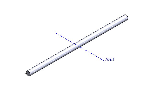
As seen in the image above, when the axis of rotation is perpendicular to the length, but is touching at the middle of the rod, then the equation would be: [math]\displaystyle{ I = \frac{1}{12}ML^2 }[/math]
where:
- I is the moment of inertia
- M is the mass of the object being rotated
- L is the length of the rod

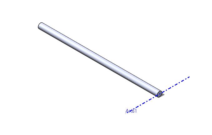
As seen in the image above, when the axis of rotation is perpendicular to the length, but is touching at one end of the rod, then the equation would be:
[math]\displaystyle{ I = \frac{1}{3}ML^2 }[/math]
where:
- I is the moment of inertia
- M is the mass of the object being rotated
- L is the length of the rod
Examples
- Calculate the kinetic energy of a rod rotating about its end given that the rod has mass 200 kg, rotational velocity of 12 m/s, and length 15m, and radius 0.5m:
- First, the equation that equals kinetic energy in rotational motion is [math]\displaystyle{ KE = \frac{1}{2}*I*ω^2 }[/math] where [math]\displaystyle{ I = \frac{1}{4}*M*R^2 + \frac{1}{3}*M*L^2 }[/math]
- Thus, finding I: [math]\displaystyle{ I = \frac{1}{4}*200*0.5^2 + \frac{1}{3}*200*10^2 }[/math]
- [math]\displaystyle{ I = 6679.166 kg*m^2 }[/math]
- Thus [math]\displaystyle{ KE = \frac{1}{2}*6679.166 *kg*m^2*(12 \frac{m}{s})^2 }[/math]
- [math]\displaystyle{ KE = 480900 J }[/math]
- Calculate the kinetic energy of a cylindrical piston rotating about its central axis given that the rod has mass 100 kg, rotational velocity of 2 m/s, and radius 5m
- [math]\displaystyle{ KE = \frac{1}{2}*I*ω^2 }[/math] where [math]\displaystyle{ I = \frac{1}{2}*M*R^2 }[/math]
- [math]\displaystyle{ I = \frac{1}{2}*100*5^2 }[/math]
- [math]\displaystyle{ I = 125 kg*m^2 }[/math]
- [math]\displaystyle{ KE = \frac{1}{2}*125 *kg*100^2*(2 \frac{m}{s})^2 }[/math]
- [math]\displaystyle{ KE = 25000 J }[/math]
Connectedness
- How is this topic connected to something that you are interested in?
Moments of inertia are important because they can be used to calculate kinetic energy of solid objects. These can be used in real life scenarios like wind turbines. The calculation of the moment of inertia for the blades can be used to find the amount of force need to still or to start the motion of the blades.
See also
You can find more information in the text book about moments of inertia for different sized objects.
External links
https://en.wikipedia.org/wiki/List_of_moments_of_inertia
http://hyperphysics.phy-astr.gsu.edu/hbase/mi.html
https://www.quora.com/What-is-an-explanation-in-simple-words-of-the-moment-of-inertia
http://www.engineeringtoolbox.com/moment-inertia-torque-d_913.html