Potential Energy for a Magnetic Dipole: Difference between revisions
Thenderlong3 (talk | contribs) No edit summary |
Thenderlong3 (talk | contribs) No edit summary |
||
| (16 intermediate revisions by the same user not shown) | |||
| Line 2: | Line 2: | ||
==The Main Idea== | ==The Main Idea== | ||
If a magnetic dipole is allowed to pivot freely without any outside forces, then it will match it's alignment with the applied magnetic field. The system favors a state of lower potential so the aligned magnetic dipole is associated with a lower potential energy in the applied magnetic field. | If a magnetic dipole is allowed to pivot freely without any outside forces, then it will match it's alignment with the applied magnetic field. The system favors a state of lower potential so the aligned magnetic dipole is associated with a lower potential energy in the applied magnetic field. Think of how a magnets interact with each other when inched closer to each other. They'll align in a way so that the north and south ends point in the same direction or have the north end of one magnet touching the south end of the other magnet (state of lowest potential). | ||
===A Mathematical Model=== | |||
By calculating how much work it takes to move a magnetic dipole out of alignment, we can determine the increased potential energy for that dipole. | |||
Let's take a look at a rectangular circuit on a horizontal axle in a magnetic field pictured below. | |||
[[File:physics_potential_energy2.png]] | |||
Now let's look at this system from the side. | |||
[[File:physics_potential_energy3.png]] | |||
We can see that the magnetic force acting on the circuit pushes the circuit out horizontally. The magnetic force is trying to make the circuit's magnetic dipole moment, μ, point in the same direction of the magnetic field. We can measure the amount of work it takes to move the circuit from an initial angle of θ<sub>i</sub> to a final angle of θ<sub>f</sub>. The work done by pushing the circuit out of alignment changes the magnetic potential energy of the system. | |||
As we push the circuit to rotate a angle of dθ around it's horizontal axis, the total distance that the force is exerted on one side of the circuit is equal to (h/2)*dθ. Keep in mind though that we are exerted force on both sides of the circuit. In the diagram this is indicated as Force by Us. We will have to determine the total amount of work done by using an integral because the force exerted depends on the value of θ and θ increases as we push the circuit more and more out of alignment. | |||
== | <p><math>Work = ΔU_m = \int\limits_{θ_i}^{θ_f}\ 2IwBsinθ(\frac{h}{2}dθ) = IwhB \int\limits_{θ_i}^{θ_f}\ sinθ dθ </math> | ||
</p> | |||
Where <math>IwBsinθ</math> is the perpendicular force exerted on only one side of the circuit. We are pushing on both sides so we multiply that by 2. <math>(\frac{h}{2}dθ)</math> is the distance that the force is exerted. | |||
<p><math>ΔU_m = IwhB[-cosθ]_{θ_i}^{θ_f} = -IwhB[cosθ_f - cosθ_i]</math> | |||
</p> | |||
<p> | |||
<math> | |||
ΔU_m = Δ(-μBcosθ)</math> since <math>μ = IA = Iwh | |||
</math> | |||
</p> | |||
so the potential energy for a dipole is | |||
<math> | |||
U_m = -μBcosθ | |||
</math>. | |||
= | Potential energy for a dipole can also be written as the dot product <math>U_m = -\overrightarrow{μ} \bullet \overrightarrow{B}\ </math>. | ||
== | ==Examples== | ||
Let's now envision two magnets interacting with each other. | |||
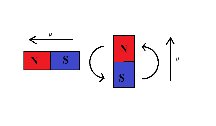
Knowing what we know now about the potential energy of a magnetic dipole, we can see why magnets move each other. Systems tend to favor states of low potential energy so when a magnet is inched closer to another magnet, their dipoles will align so that the potential energy takes on a negative value (state with the lowest potential energy). This action is illustrated below. | |||
[[File:physics_potential_energy4.png]] | |||
As the magnet on the left is held and inched closer to the magnet on the right, the magnet on the right will turn so that the magnetic dipoles align with each other. | |||
---- | |||
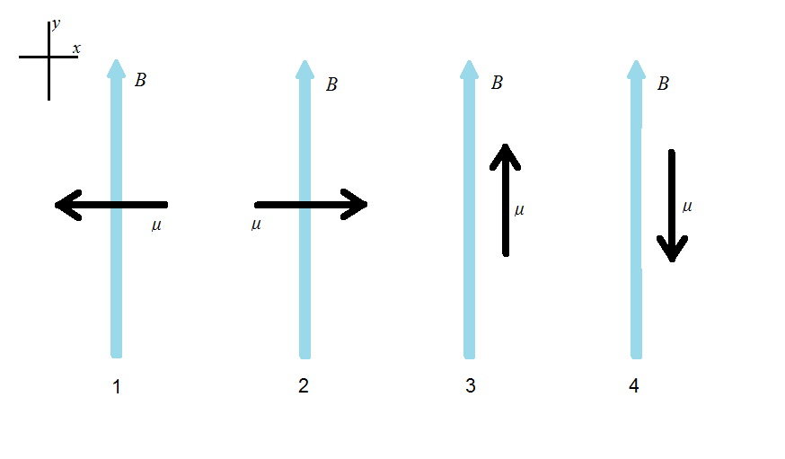
Now let's look at the dipole moments and the magnetic field below. How would we go about ranking the potential energy from of each system from greatest to smallest. | |||
[[File:physics_potential_energy5.png]] | |||
When finding the potential energy keep in mind that there is a negative sign in front of the dot product of dipole moment and magnetic field. That being said System 4 would have the largest potential energy because the dot product of the two vectors would yield a negative value in the y-component. This system would be very unstable and if we were to move the dipole moment ever so slightly, it would immediately turn to point the same exact way as the magnetic field. System 1 & 2 would have the same potential energy of 0. When finding the dot product of System 3, we would get a positive value, but with the negative sign in the front of the formula, we have a negative potential energy. So system 3 shows the most stable and desired state. So the ranking of the potential energies would be 4 > 1 = 2 > 3. | |||
== | == See also == | ||
Here are some other resources that may help. | |||
<p>[http://www.physicsbook.gatech.edu/Potential_Energy Potential Energy]</p> | |||
<p>[http://hyperphysics.phy-astr.gsu.edu/hbase/magnetic/magfor.html Magnetic Forces]</p> | |||
<p>[http://www.physicsbook.gatech.edu/Magnetic_Dipole_Moment Magnetic Dipole Moment]</p> | |||
<p>[http://www.physicsbook.gatech.edu/Magnetic_Field Magnetic Field]</p> | |||
<p>[http://www.physicsbook.gatech.edu/Work Work]</p> | |||
== References == | |||
Chabay, Ruth, and Bruce Sherwood. "Magnetic Force." Matter & Interactions. Fourth ed. Vol. 2. Hoboken: John Wiler & Sons, 2015. 829-833. Print | |||
Latest revision as of 18:01, 3 December 2015
Page Claimed by Thomas Henderlong
The Main Idea
If a magnetic dipole is allowed to pivot freely without any outside forces, then it will match it's alignment with the applied magnetic field. The system favors a state of lower potential so the aligned magnetic dipole is associated with a lower potential energy in the applied magnetic field. Think of how a magnets interact with each other when inched closer to each other. They'll align in a way so that the north and south ends point in the same direction or have the north end of one magnet touching the south end of the other magnet (state of lowest potential).
A Mathematical Model
By calculating how much work it takes to move a magnetic dipole out of alignment, we can determine the increased potential energy for that dipole.
Let's take a look at a rectangular circuit on a horizontal axle in a magnetic field pictured below.
Now let's look at this system from the side.
We can see that the magnetic force acting on the circuit pushes the circuit out horizontally. The magnetic force is trying to make the circuit's magnetic dipole moment, μ, point in the same direction of the magnetic field. We can measure the amount of work it takes to move the circuit from an initial angle of θi to a final angle of θf. The work done by pushing the circuit out of alignment changes the magnetic potential energy of the system.
As we push the circuit to rotate a angle of dθ around it's horizontal axis, the total distance that the force is exerted on one side of the circuit is equal to (h/2)*dθ. Keep in mind though that we are exerted force on both sides of the circuit. In the diagram this is indicated as Force by Us. We will have to determine the total amount of work done by using an integral because the force exerted depends on the value of θ and θ increases as we push the circuit more and more out of alignment.
[math]\displaystyle{ Work = ΔU_m = \int\limits_{θ_i}^{θ_f}\ 2IwBsinθ(\frac{h}{2}dθ) = IwhB \int\limits_{θ_i}^{θ_f}\ sinθ dθ }[/math]
Where [math]\displaystyle{ IwBsinθ }[/math] is the perpendicular force exerted on only one side of the circuit. We are pushing on both sides so we multiply that by 2. [math]\displaystyle{ (\frac{h}{2}dθ) }[/math] is the distance that the force is exerted.
[math]\displaystyle{ ΔU_m = IwhB[-cosθ]_{θ_i}^{θ_f} = -IwhB[cosθ_f - cosθ_i] }[/math]
[math]\displaystyle{ ΔU_m = Δ(-μBcosθ) }[/math] since [math]\displaystyle{ μ = IA = Iwh }[/math]
so the potential energy for a dipole is [math]\displaystyle{ U_m = -μBcosθ }[/math].
Potential energy for a dipole can also be written as the dot product [math]\displaystyle{ U_m = -\overrightarrow{μ} \bullet \overrightarrow{B}\ }[/math].
Examples
Let's now envision two magnets interacting with each other.
Knowing what we know now about the potential energy of a magnetic dipole, we can see why magnets move each other. Systems tend to favor states of low potential energy so when a magnet is inched closer to another magnet, their dipoles will align so that the potential energy takes on a negative value (state with the lowest potential energy). This action is illustrated below.
As the magnet on the left is held and inched closer to the magnet on the right, the magnet on the right will turn so that the magnetic dipoles align with each other.
Now let's look at the dipole moments and the magnetic field below. How would we go about ranking the potential energy from of each system from greatest to smallest.
When finding the potential energy keep in mind that there is a negative sign in front of the dot product of dipole moment and magnetic field. That being said System 4 would have the largest potential energy because the dot product of the two vectors would yield a negative value in the y-component. This system would be very unstable and if we were to move the dipole moment ever so slightly, it would immediately turn to point the same exact way as the magnetic field. System 1 & 2 would have the same potential energy of 0. When finding the dot product of System 3, we would get a positive value, but with the negative sign in the front of the formula, we have a negative potential energy. So system 3 shows the most stable and desired state. So the ranking of the potential energies would be 4 > 1 = 2 > 3.
See also
Here are some other resources that may help.
References
Chabay, Ruth, and Bruce Sherwood. "Magnetic Force." Matter & Interactions. Fourth ed. Vol. 2. Hoboken: John Wiler & Sons, 2015. 829-833. Print


