Current in a RL Circuit: Difference between revisions
Jake.sebring (talk | contribs) No edit summary |
Jake.sebring (talk | contribs) No edit summary |
||
| (25 intermediate revisions by the same user not shown) | |||
| Line 1: | Line 1: | ||
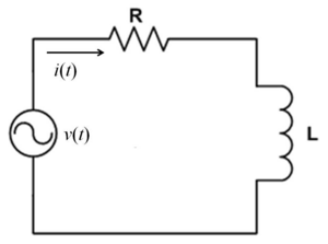
A resistor-inductor circuit is an electric circuit that contains both a resistor, R, and an inductor, L, and is powered by a current source such as a battery. The energy conservation equation for a RL circuit is typically of the form: '''''ΔV_battery + ΔV_resistor + ΔV_inductor = 0''''' [[File:RL Circuit.png|300px|right]] | A resistor-inductor circuit is an electric circuit that contains both a resistor, R, and an inductor, L, and is powered by a current or voltage source such as a battery. The energy conservation equation for a RL circuit is typically of the form: '''''ΔV_battery + ΔV_resistor + ΔV_inductor = 0''''' [[File:RL Circuit.png|300px|right]] | ||
==The Main Idea== | ==The Main Idea== | ||
The three basic elements of an electrical circuit are the resistor, R, inductor, L, and capacitor, C. There are four unique combinations of these elements - the RL, LC, RC, and RLC circuit. Each circuit behaves slightly different in order to act as a passive filter to significantly contribute to electronics. | |||
Assume that the circuit diagram is reflecting the state of the circuit some amount of time after the closing of a switch, where time = 0 seconds at the close of the switch. Under this assumption, the current, I, in the RL circuit can be modeled using the equation: | |||
'''''I = (Emf_battery/R)*[1-e^-(R/L)t].''''' | |||
Thus, I = Emf_battery / R for big values of t, when the circuit exhibits a steady-state current. At this later time, the circuit would behave as if the inductor is not present because the inductor is no longer producing emf, and there is no flux. | |||
Given this inductor effect, the inductor causes the current to slowly build up to the steady-state. This is clear in the graph of current versus time below. | |||
[[File:Current.png|250px||right]] | |||
If the circuit contained only a resistor and battery, the current would build up much quicker. So, it is fair to state that the inductor opposes the buildup of current as described by Lenz's Law. In order to characterize the amount of time it takes for the current to build up, there is a time constant that is calculated as L/R. At this time point, the exponential factor is proven to be 1/e = 0.37. | |||
===A Mathematical Model=== | ===A Mathematical Model=== | ||
| Line 13: | Line 25: | ||
'''''Emf_battery - RI - L(dI/dt) = 0''''' | '''''Emf_battery - RI - L(dI/dt) = 0''''' | ||
'''''I = (Emf_battery/R)*[1-e^-(R/L)t]''''' | |||
At t >> 0, '''''I = (Emf_battery/R)''''' | |||
==Examples== | ==Examples== | ||
| Line 22: | Line 36: | ||
===Simple=== | ===Simple=== | ||
[[example.png|250px|right]] | |||
===Middling=== | ===Middling=== | ||
===Difficult=== | ===Difficult=== | ||
==Connectedness== | ==Connectedness== | ||
1. How is this topic connected to something that you are interested in? | |||
It is interesting that the presence of the inductor in the RL circuit can cause certain negative effects such as a spark that is created when opening the switch after a long period of time. | |||
2. How is it connected to your major? | |||
This is relevant to biomedical engineering because the behavior of the current in the RL circuit can be useful in several applications where the medical device needs to communicate to a remote data collector in order to transmit medical data through a radio frequency. | |||
3. Is there an interesting industrial application? | |||
A common industrial application of the RL circuit is as a direct current power supply to radio frequency amplifiers. In this case, the inductor is needed to block the radio frequency from returning to the power supply. | |||
== | ==History== | ||
A French scientist, Felix Savary, was the first to discover the electrical oscillations of a capacitor. This discovery was made during an experiment where there was a needle with a piece of wire wrapped around it. Savary observed that the needle move back and forth. Felix hypothesized that this effect occurred because of a current in the wire. The current caused oscillations which magnetized the needle back and forth until the current decreases. | |||
[[File:Savary.png|200px|right]] | |||
In the end of the 19th century, this theory was put into use in radio transmitters that allowed the receiver to be tuned in. | |||
===External links=== | ===External links=== | ||
[http:// | [http://hyperphysics.phy-astr.gsu.edu/hbase/electric/rlimp.html] Resistor-Inductor AC Behavior | ||
==References== | |||
1. http://cnx.org/contents/7025ec30-2efe-449f-8475-089c3063433f@3.1:9/MATH-1508-(Laboratory)-Enginee | |||
2. http://www.physics.rutgers.edu/ugrad/205/manuals/am.pdf | |||
3. http://www.physics.sjsu.edu/becker/physics51/31_08_R-L_circuit_i_vs_t.JPG | |||
http://www.physics. | |||
[[Category:Simple Circuits]] | [[Category:Simple Circuits]] | ||
Latest revision as of 09:08, 6 December 2015
A resistor-inductor circuit is an electric circuit that contains both a resistor, R, and an inductor, L, and is powered by a current or voltage source such as a battery. The energy conservation equation for a RL circuit is typically of the form: ΔV_battery + ΔV_resistor + ΔV_inductor = 0

The Main Idea
The three basic elements of an electrical circuit are the resistor, R, inductor, L, and capacitor, C. There are four unique combinations of these elements - the RL, LC, RC, and RLC circuit. Each circuit behaves slightly different in order to act as a passive filter to significantly contribute to electronics.
Assume that the circuit diagram is reflecting the state of the circuit some amount of time after the closing of a switch, where time = 0 seconds at the close of the switch. Under this assumption, the current, I, in the RL circuit can be modeled using the equation:
I = (Emf_battery/R)*[1-e^-(R/L)t].
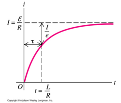
Thus, I = Emf_battery / R for big values of t, when the circuit exhibits a steady-state current. At this later time, the circuit would behave as if the inductor is not present because the inductor is no longer producing emf, and there is no flux.
Given this inductor effect, the inductor causes the current to slowly build up to the steady-state. This is clear in the graph of current versus time below.

If the circuit contained only a resistor and battery, the current would build up much quicker. So, it is fair to state that the inductor opposes the buildup of current as described by Lenz's Law. In order to characterize the amount of time it takes for the current to build up, there is a time constant that is calculated as L/R. At this time point, the exponential factor is proven to be 1/e = 0.37.
A Mathematical Model
ΔV_battery + ΔV_resistor + ΔV_inductor = 0
Emf_battery - RI - L(dI/dt) = 0
I = (Emf_battery/R)*[1-e^-(R/L)t]
At t >> 0, I = (Emf_battery/R)
Examples
Be sure to show all steps in your solution and include diagrams whenever possible
Simple
Middling
Difficult
Connectedness
1. How is this topic connected to something that you are interested in?
It is interesting that the presence of the inductor in the RL circuit can cause certain negative effects such as a spark that is created when opening the switch after a long period of time.
2. How is it connected to your major?
This is relevant to biomedical engineering because the behavior of the current in the RL circuit can be useful in several applications where the medical device needs to communicate to a remote data collector in order to transmit medical data through a radio frequency.
3. Is there an interesting industrial application?
A common industrial application of the RL circuit is as a direct current power supply to radio frequency amplifiers. In this case, the inductor is needed to block the radio frequency from returning to the power supply.
History
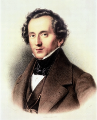
A French scientist, Felix Savary, was the first to discover the electrical oscillations of a capacitor. This discovery was made during an experiment where there was a needle with a piece of wire wrapped around it. Savary observed that the needle move back and forth. Felix hypothesized that this effect occurred because of a current in the wire. The current caused oscillations which magnetized the needle back and forth until the current decreases.

In the end of the 19th century, this theory was put into use in radio transmitters that allowed the receiver to be tuned in.
External links
[1] Resistor-Inductor AC Behavior
References
1. http://cnx.org/contents/7025ec30-2efe-449f-8475-089c3063433f@3.1:9/MATH-1508-(Laboratory)-Enginee
2. http://www.physics.rutgers.edu/ugrad/205/manuals/am.pdf
3. http://www.physics.sjsu.edu/becker/physics51/31_08_R-L_circuit_i_vs_t.JPG