Transformers (Circuits): Difference between revisions
| (85 intermediate revisions by 2 users not shown) | |||
| Line 1: | Line 1: | ||
Electricity sent through power lines is transmitted with high voltages through long thick power lines because wires have a resistance that causes power loss at a rate proportional to the current squared. By transmitting at a high voltage, energy loss is minimized. Home appliances however operate at much lower voltages. Something is needed to convert the power to a high current, low voltage power that home appliances can use. This conversion from high voltage to low voltage, and vice versa, is accomplished by a transformer. | |||
==Background== | |||
=== | ===Inductance=== | ||
Currents can be induced (produced) by changing the current through a coil. This is due to the changing magnetic field <math>\textstyle (dB/dt)</math> produced by varying the current through the coil. We know from the Maxwell-Faraday Law of Maxwell's Equations: | |||
<math align="center">|emf| = \oint \overrightarrow{E}_{NC} \cdot d\overrightarrow{l} = \left | \frac{d\phi_{mag}}{dt} \right \vert </math> | |||
Or that a changing magnetic field through an area produces a non-Coloumb electric field. | |||
=== | ===Mathematical Formulae=== | ||
Before moving on to a discussion of the mathematics of transformers, here are some formulas it will be helpful to recall: | |||
* Magnetic Field Inside a Solenoid: <math>B=\frac{\mu_0 N I}{d}</math> | |||
::Where <math>\textstyle N</math> is the number of coils and <math>\textstyle d</math> is the length of the solenoid. | |||
= | * Magnitude of self-induced emf: <math>\textstyle \left|emf_{ind}\right \vert=L\left|\frac{d I}{d t} \right \vert</math> | ||
:: Where <math>L</math> is the proportionality constant called the "inductance" or "self-inductance" which equals <math>\textstyle \frac{\mu_0 N^2}{d}\pi R^2</math> | |||
*Expanding this, we get the self-induced emf in a solenoid is: <math>\textstyle emf= \frac{\mu_0 N^2}{d}\pi R^2 \frac{d I}{d t}</math> | |||
* Finally, remember your units. <math>emf</math> is measured in volts, self-inductance is <math>\textstyle(V•s/A)</math> or the "henry" (H), and <math>B</math> is measured in Tesla (T) or <math>\textstyle(\frac{kg}{s^2 A})</math> | |||
==How They Work== | |||
Conversion from high to low, or low to high voltage can be accomplished using the principles discussed above. Consider a solenoid with <math>N_1=100</math> turns around a hollow cylinder of length <math>d=.3 m</math>. Now wrap <math>N_2 = 200</math> turns around this solenoid to form the secondary coil. If an ''alternating current'' is run through the primary coil, we get a non-zero <math>\textstyle\frac{d I}{d t}</math>We can now calculate the potential difference across each coil. | |||
== | ===Primary Coil=== | ||
As stated [[#Mathematical Formulae|above]], the induced emf in the primary coil is <math>L\left|\frac{d I}{d t} \right \vert</math>. Expanding this and substituting <math>A=\pi R^2</math> for the area, we get a potential difference across the primary coil of <math>\textstyle A(\mu_0 N_1^2 /d)dI/dt</math>. | |||
The | ===Secondary Coil=== | ||
A current is induced in the secondary coil by the changing magnetic field produced by the primary coil. The magnetic field is <math>\textstyle B = \mu_0 N_1 I/d</math> and it is changing across area <math>A</math> (which is only the area of the inner coil, not the outer secondary coil. So the emf in one turn of the secondary coil is <math>A dB/dt</math>. We have <math>N_2</math> secondary coils, so the emf is <math>N_2 AdB/dt</math>. If we expand out our <math>dB/dt</math> term, we can get the emf across the second coil in a formula similar to the emf across the primary coil: <math>emf_{sec} = N_2A(\mu_0N_1/d)dI/dt</math>. | |||
=== | ===Voltage Ratio=== | ||
We now can see that the ratio of the secondary to primary emf is <math>emf_{pri}/emf_{sec}</math>. This yields: | |||
<math>\frac {N_2A(\mu_0N_1/d)dI/dt}{A(\mu_0 N_1^2 /d)dI/dt}</math> which cancels and leaves <math>\frac {N_2}{N_1}</math> or in this case <math>\frac{200}{100}</math>. | |||
This transformer would create a emf 2 times the emf in the primary coil. Because we can't create energy from nothing, power (<math>I\Delta V</math>) must be conserved; the double voltage in the secondary coil is accompanied by a current of half the strength of the primary coil. | |||
The transformer described above is called a "step-up" transformer because it "ups" the voltage. There are also "step-down" transformers which reduce the voltage and have fewer turns on the secondary coil than primary coil. | |||
''' | ==Circuit Diagrams== | ||
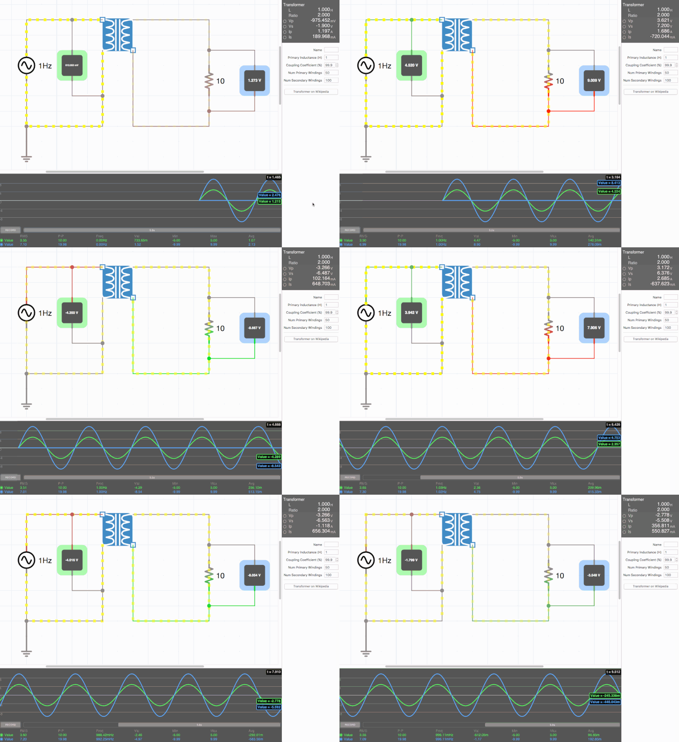
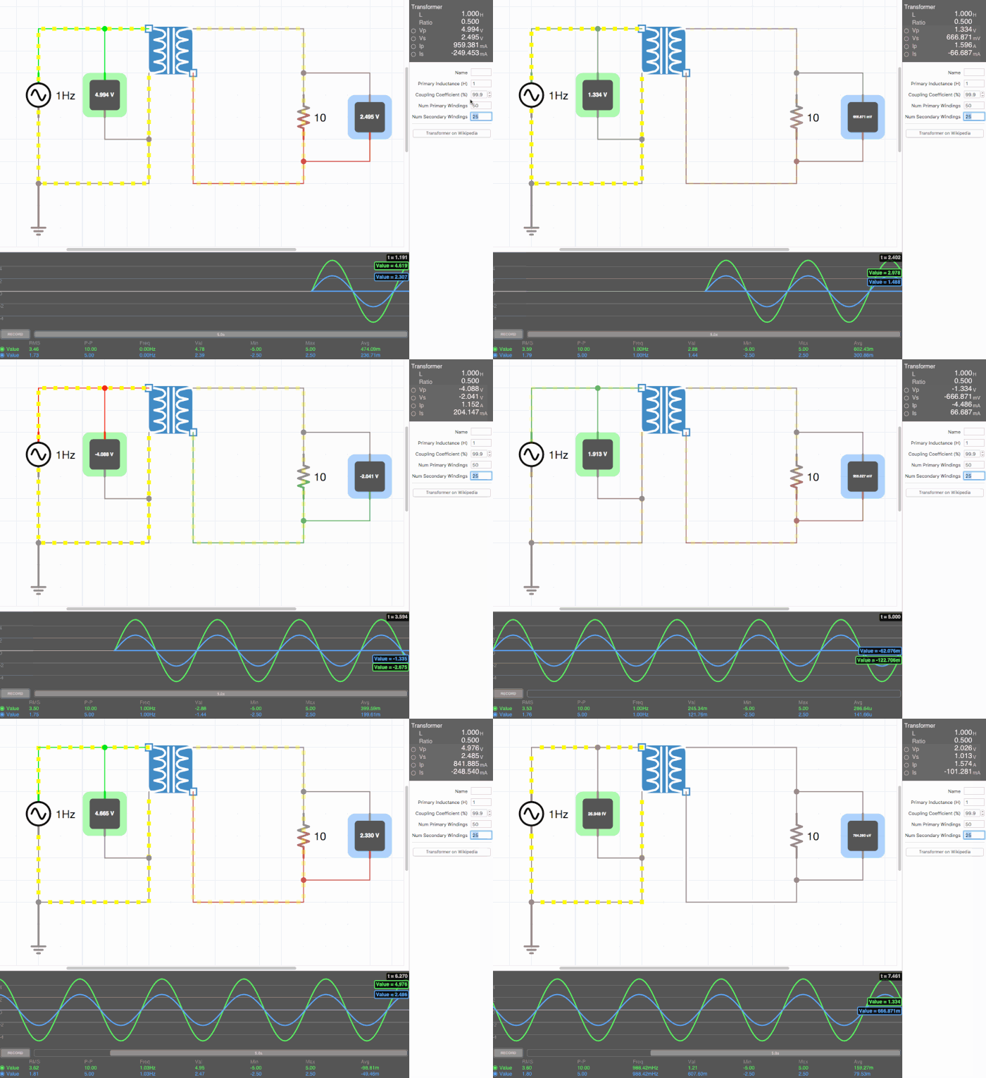
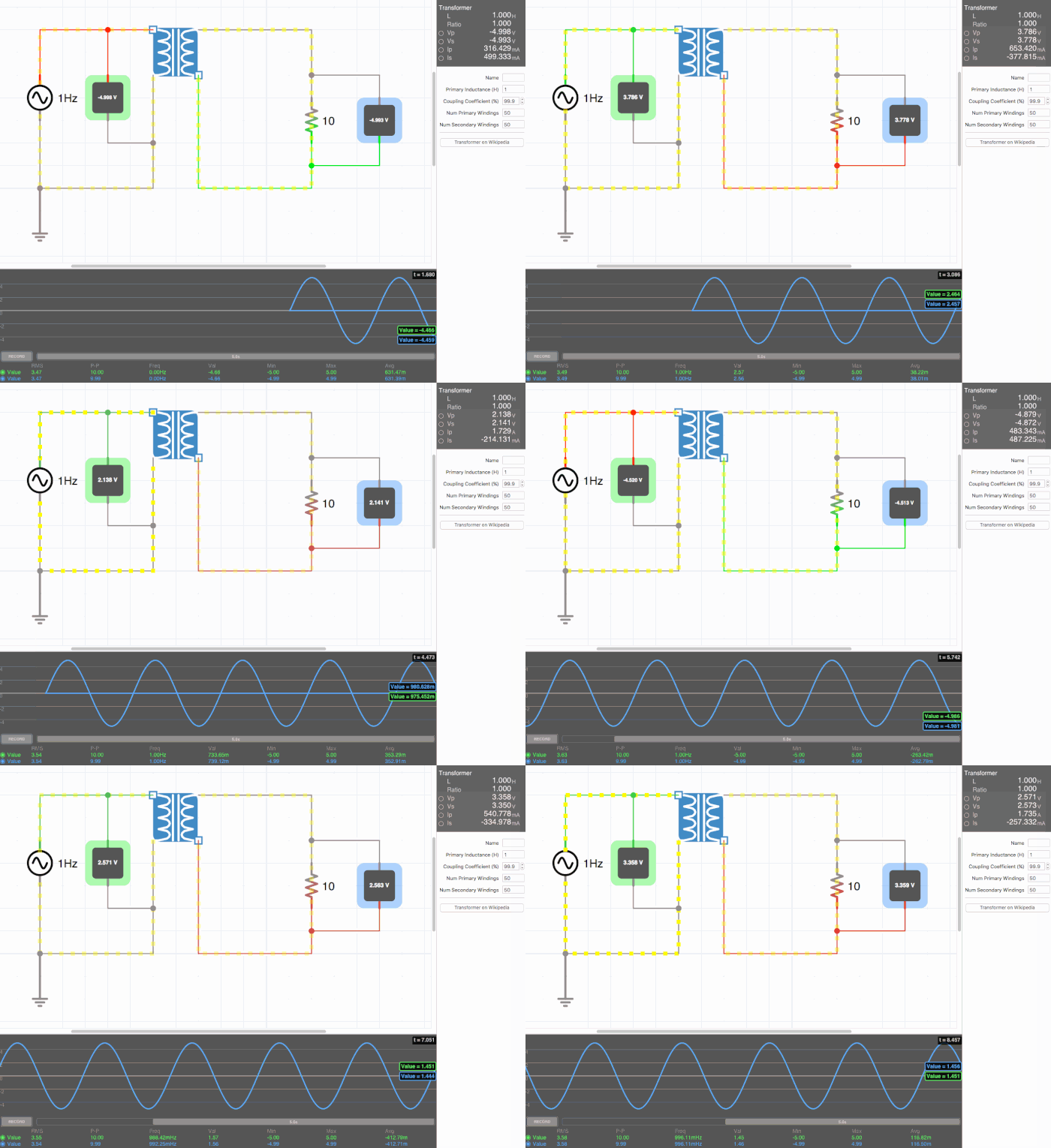
Below are animated circuit diagrams for a step-up transformer, step-down transformer, and even a somewhat pointless transformer that has a 1:1 voltage ratio. The right side panel lists the properties of the transformer. The primary inductance and coupling coefficient are beyond the scope of my knowledge. However I did enough research to know that the ''Coupling Coefficient'' is some property of a transformer derived from the self inductance of each coil. I believe for most discussions on transformers, the "ideal" coupling coefficient is 100%. The waveform is graphing the voltage of the left loop (blue) and voltage of the right loop (green). | |||
[[File:step_up.gif|500px|border|frame|center|A step-up transformer that doubles voltage and halves current]] | |||
[[File:step_down.gif|500px|border|frame|center|A step-down transformer that halves voltage and double current]] | |||
[[File:constant.gif|500px|border|frame|center|A 1:1 transformer. Here the green line isn't visible on the waveform because the voltages are identical.]] | |||
==Connectedness== | ==Connectedness== | ||
:'''1. How is this topic connected to something that you are interested in?''' | |||
Although Dr. Greco said he found the circuits chapter and material dull, as a Computer Science major with an interest in Electrical Engineering and tinkering with hardware, I thought it was a great practical part of the course. Our textbook ''Electric Potential. In Matter & interactions (4th ed.)'' introduces transformers in the context of induction and Faraday in a more conceptual sense. I believed they should also be shown alongside circuits to demonstrate their practicality. It really helped with my understanding the view the setup and waveform of a circuit involving transformers. | |||
I even tried to add a bridge rectifier and regulator to the circuit to show the AC being transformed back into DC. My circuits knowledge is somewhat limited and I was unable to properly connect this circuit. | |||
:'''2. How is it connected to your major?''' | |||
In today's world of open source hardware and software, it is very important for a Computer Science major to understand circuits beyond a basic level and be able to incorporate circuits and moving parts into their work. With Raspberry Pis, Arduinos, and everything else the internet has to offer, a CS major is severely limiting themselves by not studying topics like theses. | |||
:'''3. Is there an interesting industrial application?''' | |||
I think the interesting thing about industrial applications is how transformers appear in such a simple context in many power cords for appliances today. I remember back to my first interaction with one: Years ago at a friend's house we were playing songs on his electrical keyboard. At a point, we decided to move the keyboard and in the process broke the plastic casing off the transformer of the power cord. I was young, so didn't recognize it as a danger or issue at the time. I can vividly remember the copper coils (I think). At any rate, I plugged it in and was touching the coils and got an arm numbing shock. But my shock boils down to just a simple transformer that any Physics 2 student could make and understand. | |||
==See also== | |||
#[[Faraday's Law]] This will give you a general understanding of Faraday's Law, which is the basis behind transformer technology. | |||
#[[Inductance]] A more in depth look at Inductance, a direct consequence of Faraday's Law. | |||
#[[Gauss's Flux Theorem]] Changing the flux of a magnetic field around a coil will induce voltage. | |||
#[[Transformers from a physics standpoint]] Detail on the material properties and physics of transformers, outside the scope of circuits. | |||
===Further reading=== | ===Further reading=== | ||
| Line 60: | Line 76: | ||
Books, Articles or other print media on this topic | Books, Articles or other print media on this topic | ||
== | ==References== | ||
Chabay, R., & Sherwood, B. (2015). Electric Potential. In Matter & interactions (4th ed., Vol. Two, pp. 917-921). Danvers, Massachusetts: J. Wiley & sons. | |||
[http://icircuitapp.com iCircuit - Electronic Circuit Simulator and Designer (available for Windows, Mac, and iOS)] | |||
http:// | |||
[[Category: | [[Category: Simple Circuits]] | ||
Latest revision as of 11:32, 8 December 2015
Electricity sent through power lines is transmitted with high voltages through long thick power lines because wires have a resistance that causes power loss at a rate proportional to the current squared. By transmitting at a high voltage, energy loss is minimized. Home appliances however operate at much lower voltages. Something is needed to convert the power to a high current, low voltage power that home appliances can use. This conversion from high voltage to low voltage, and vice versa, is accomplished by a transformer.
Background
Inductance
Currents can be induced (produced) by changing the current through a coil. This is due to the changing magnetic field [math]\displaystyle{ \textstyle (dB/dt) }[/math] produced by varying the current through the coil. We know from the Maxwell-Faraday Law of Maxwell's Equations:
[math]\displaystyle{ |emf| = \oint \overrightarrow{E}_{NC} \cdot d\overrightarrow{l} = \left | \frac{d\phi_{mag}}{dt} \right \vert }[/math]
Or that a changing magnetic field through an area produces a non-Coloumb electric field.
Mathematical Formulae
Before moving on to a discussion of the mathematics of transformers, here are some formulas it will be helpful to recall:
- Magnetic Field Inside a Solenoid: [math]\displaystyle{ B=\frac{\mu_0 N I}{d} }[/math]
- Where [math]\displaystyle{ \textstyle N }[/math] is the number of coils and [math]\displaystyle{ \textstyle d }[/math] is the length of the solenoid.
- Magnitude of self-induced emf: [math]\displaystyle{ \textstyle \left|emf_{ind}\right \vert=L\left|\frac{d I}{d t} \right \vert }[/math]
- Where [math]\displaystyle{ L }[/math] is the proportionality constant called the "inductance" or "self-inductance" which equals [math]\displaystyle{ \textstyle \frac{\mu_0 N^2}{d}\pi R^2 }[/math]
- Expanding this, we get the self-induced emf in a solenoid is: [math]\displaystyle{ \textstyle emf= \frac{\mu_0 N^2}{d}\pi R^2 \frac{d I}{d t} }[/math]
- Finally, remember your units. [math]\displaystyle{ emf }[/math] is measured in volts, self-inductance is [math]\displaystyle{ \textstyle(V•s/A) }[/math] or the "henry" (H), and [math]\displaystyle{ B }[/math] is measured in Tesla (T) or [math]\displaystyle{ \textstyle(\frac{kg}{s^2 A}) }[/math]
How They Work
Conversion from high to low, or low to high voltage can be accomplished using the principles discussed above. Consider a solenoid with [math]\displaystyle{ N_1=100 }[/math] turns around a hollow cylinder of length [math]\displaystyle{ d=.3 m }[/math]. Now wrap [math]\displaystyle{ N_2 = 200 }[/math] turns around this solenoid to form the secondary coil. If an alternating current is run through the primary coil, we get a non-zero [math]\displaystyle{ \textstyle\frac{d I}{d t} }[/math]We can now calculate the potential difference across each coil.
Primary Coil
As stated above, the induced emf in the primary coil is [math]\displaystyle{ L\left|\frac{d I}{d t} \right \vert }[/math]. Expanding this and substituting [math]\displaystyle{ A=\pi R^2 }[/math] for the area, we get a potential difference across the primary coil of [math]\displaystyle{ \textstyle A(\mu_0 N_1^2 /d)dI/dt }[/math].
Secondary Coil
A current is induced in the secondary coil by the changing magnetic field produced by the primary coil. The magnetic field is [math]\displaystyle{ \textstyle B = \mu_0 N_1 I/d }[/math] and it is changing across area [math]\displaystyle{ A }[/math] (which is only the area of the inner coil, not the outer secondary coil. So the emf in one turn of the secondary coil is [math]\displaystyle{ A dB/dt }[/math]. We have [math]\displaystyle{ N_2 }[/math] secondary coils, so the emf is [math]\displaystyle{ N_2 AdB/dt }[/math]. If we expand out our [math]\displaystyle{ dB/dt }[/math] term, we can get the emf across the second coil in a formula similar to the emf across the primary coil: [math]\displaystyle{ emf_{sec} = N_2A(\mu_0N_1/d)dI/dt }[/math].
Voltage Ratio
We now can see that the ratio of the secondary to primary emf is [math]\displaystyle{ emf_{pri}/emf_{sec} }[/math]. This yields:
[math]\displaystyle{ \frac {N_2A(\mu_0N_1/d)dI/dt}{A(\mu_0 N_1^2 /d)dI/dt} }[/math] which cancels and leaves [math]\displaystyle{ \frac {N_2}{N_1} }[/math] or in this case [math]\displaystyle{ \frac{200}{100} }[/math].
This transformer would create a emf 2 times the emf in the primary coil. Because we can't create energy from nothing, power ([math]\displaystyle{ I\Delta V }[/math]) must be conserved; the double voltage in the secondary coil is accompanied by a current of half the strength of the primary coil.
The transformer described above is called a "step-up" transformer because it "ups" the voltage. There are also "step-down" transformers which reduce the voltage and have fewer turns on the secondary coil than primary coil.
Circuit Diagrams
Below are animated circuit diagrams for a step-up transformer, step-down transformer, and even a somewhat pointless transformer that has a 1:1 voltage ratio. The right side panel lists the properties of the transformer. The primary inductance and coupling coefficient are beyond the scope of my knowledge. However I did enough research to know that the Coupling Coefficient is some property of a transformer derived from the self inductance of each coil. I believe for most discussions on transformers, the "ideal" coupling coefficient is 100%. The waveform is graphing the voltage of the left loop (blue) and voltage of the right loop (green).


Connectedness
- 1. How is this topic connected to something that you are interested in?
Although Dr. Greco said he found the circuits chapter and material dull, as a Computer Science major with an interest in Electrical Engineering and tinkering with hardware, I thought it was a great practical part of the course. Our textbook Electric Potential. In Matter & interactions (4th ed.) introduces transformers in the context of induction and Faraday in a more conceptual sense. I believed they should also be shown alongside circuits to demonstrate their practicality. It really helped with my understanding the view the setup and waveform of a circuit involving transformers.
I even tried to add a bridge rectifier and regulator to the circuit to show the AC being transformed back into DC. My circuits knowledge is somewhat limited and I was unable to properly connect this circuit.
- 2. How is it connected to your major?
In today's world of open source hardware and software, it is very important for a Computer Science major to understand circuits beyond a basic level and be able to incorporate circuits and moving parts into their work. With Raspberry Pis, Arduinos, and everything else the internet has to offer, a CS major is severely limiting themselves by not studying topics like theses.
- 3. Is there an interesting industrial application?
I think the interesting thing about industrial applications is how transformers appear in such a simple context in many power cords for appliances today. I remember back to my first interaction with one: Years ago at a friend's house we were playing songs on his electrical keyboard. At a point, we decided to move the keyboard and in the process broke the plastic casing off the transformer of the power cord. I was young, so didn't recognize it as a danger or issue at the time. I can vividly remember the copper coils (I think). At any rate, I plugged it in and was touching the coils and got an arm numbing shock. But my shock boils down to just a simple transformer that any Physics 2 student could make and understand.
See also
- Faraday's Law This will give you a general understanding of Faraday's Law, which is the basis behind transformer technology.
- Inductance A more in depth look at Inductance, a direct consequence of Faraday's Law.
- Gauss's Flux Theorem Changing the flux of a magnetic field around a coil will induce voltage.
- Transformers from a physics standpoint Detail on the material properties and physics of transformers, outside the scope of circuits.
Further reading
Books, Articles or other print media on this topic
References
Chabay, R., & Sherwood, B. (2015). Electric Potential. In Matter & interactions (4th ed., Vol. Two, pp. 917-921). Danvers, Massachusetts: J. Wiley & sons.
iCircuit - Electronic Circuit Simulator and Designer (available for Windows, Mac, and iOS)