RC Circuit: Difference between revisions
Mrussell38 (talk | contribs) No edit summary |
|||
| (23 intermediate revisions by 3 users not shown) | |||
| Line 1: | Line 1: | ||
Claimed by Sean Fischer Fall 2016 | |||
[[File:Rc_circuit.JPG|400px|right|]] | [[File:Rc_circuit.JPG|400px|right|]] | ||
==The Main Idea== | ==The Main Idea== | ||
| Line 25: | Line 25: | ||
===A Mathematical Model=== | ===A Mathematical Model=== | ||
These three equations are helpful in solving and understanding RC circuit problems | These three equations are helpful in solving and understanding RC circuit problems | ||
[[File:Rc123.jpg]] | |||
To find the equation for voltage versus time when charging a capacitor through a resistor, you start with rearranging the energy equation and solving for I: | To find the equation for voltage versus time when charging a capacitor through a resistor, you start with rearranging the energy equation and solving for I: | ||
[[File:Rc234.jpg]] | |||
The graph of Voltage vs. Time in a RC Circuit is given by: | |||
[[File:Outputrc.jpg]] | |||
===A Computational Model=== | |||
==A Computational Model== | |||
Using a simulation where R and C were equal, the capacitors were charged and then discharged and the two images show the voltage and current of this versus time. | Using a simulation where R and C were equal, the capacitors were charged and then discharged and the two images show the voltage and current of this versus time. | ||
For the gif below, the capacitor is charged and then discharged. This shows the voltage over time. The red line is the voltage and the gray line is the emf. | For the gif below, the capacitor is charged and then discharged. This shows the voltage over time. The red line is the voltage and the gray line is the emf. (May have to click image to see gif) | ||
[[File:rcvoltage.gif|300px|center|]] | [[File:rcvoltage.gif|300px|center|]] | ||
For the gif below, the capacitor is charged and then discharged. This shows the current over time. The blue line is the current. | For the gif below, the capacitor is charged and then discharged. This shows the current over time. The blue line is the current. (May have to click image to see gif) | ||
[[File:rccurrent.gif|300px|center|]] | [[File:rccurrent.gif|300px|center|]] | ||
| Line 87: | Line 52: | ||
===Simple=== | ===Simple=== | ||
In a circuit where time t = RC, the factor <math>{e^{\frac{-t}{RC}}}</math> has fallen from value <math>{e^0} = {1}</math> to the value: | |||
In the | |||
e^(-t/RC) = e^1 = 1/e = 1/2.718 = 0.37 | |||
Calculate the time constant for the RC circuit with R = 12 ohms and C = 1 farad. | |||
Solution: | |||
<math> {RC}= {12*1} = {12 seconds}</math> | |||
===Middling=== | |||
Using the information from the problem above: | |||
Show that the power dissipated in the bulb at t=RC is only 14% of the original power? | |||
Solution: | |||
Using <math>{IΔV} = {RI^2}</math>, reduction in current by factor of 0.37 gives a reduction in power by a factor of (0.37)^2 = 0.1369 | |||
===Difficult=== | ===Difficult=== | ||
The circuit | The best example of difficult RC circuit problems come from past exams. Take a look at this RC circuit. | ||
[[File: | [[File:Primary1.jpg]] | ||
The first step in these problems is to identify all the parts on the circuit and draw in nodes at necessary locations. You want to choose spots for the nodes where the wire splits so you can apply Kirchoff's law and relate the current at these locations. | |||
[[File:Primary2.jpg]] | |||
Once you correctly label the diagram you can begin the problem. | |||
1. Write down the three energy conservation equations for the circuit. Also write down the charge conservation equation for the circuit you would need to determine the current through the bulbs and capacitor. You do not need to solve these equations. | |||
2.Determine the initial current passing through each bulb. | |||
3. Determine the current passing through each bulb for a long time after the switch has been closed. | |||
[[File:Workwork.jpg]] | |||
==Connectedness== | ==Connectedness== | ||
1. How is this topic connected to something that you are interested in? | |||
:: I | :: I enjoy listening to music and RC circuits are used in speakers and headphones. They allow the current to be regulated and for the music to to played at the right pitch and volume. | ||
[[File:Speakercirc.jpg]] | |||
:: I'm | |||
2. How is it connected to your major? | |||
RC circuits are used to | :: I'm a Mechanical Engineering major and RC currents are directly related to every job, but in warehouses where heavy machinery and appliances are involved, RC currents are used in parts either at the warehouse or ones that are being assembled. I would be designing the machines not wiring the curcuits, but it is important to understand how the RC circuits are used in order to properly design and implement the machines. | ||
3. Is there an interesting industrial application? | |||
:: RC circuits are used as filters for almost all types of electronics. The initial input is taken across the RC circuit and the output is taken across the capacitor. This allows the capacitor in the circuit to be charged to different values and used when the desired one is obtained. It is an easy way to allow multiple energy outputs across a single circuit rather than using a bunch of different circuits. | |||
[[File:Fil42.gif]] | |||
==History== | |||
The RC circuits have been in use for a long time. Georg Simon Ohm, was someone who spent alot of time researching RC Circuits and Ohm's Law was founded by him. He did his work from 1830s-1840s and he received recognition, after a long time of being mocked by other scientists. Once his work was recognized and accepted by the scientific community people began to realize the many applications of RC circuits as filters and began to further research and implement them in their own work. | |||
== See also == | == See also == | ||
| Line 145: | Line 123: | ||
http://www.allaboutcircuits.com/textbook/alternating-current/chpt-4/series-resistor-capacitor-circuits/ | http://www.allaboutcircuits.com/textbook/alternating-current/chpt-4/series-resistor-capacitor-circuits/ | ||
http://buphy.bu.edu/~duffy/semester2/c11_RC.html | |||
http://ocw.mit.edu/courses/physics/8-022-physics-ii-electricity-and-magnetism-fall-2006/lecture-notes/lecture32.pdf | |||
==References== | ==References== | ||
http://www. | http://www.compadre.org/portal/items/detail.cfm?ID=9986 | ||
https://www.pa.msu.edu/courses/1997spring/PHY232/lectures/kirchoff/examples.html | https://www.pa.msu.edu/courses/1997spring/PHY232/lectures/kirchoff/examples.html | ||
https://openstaxcollege.org/textbooks/college-physics | |||
http://www.animations.physics.unsw.edu.au/jw/RCfilters.html | |||
[[Category:Simple Circuits]] | [[Category:Simple Circuits]] | ||
Latest revision as of 00:15, 28 November 2016
Claimed by Sean Fischer Fall 2016

The Main Idea
An RC circuit is a circuit that contains a battery with a known emf, a resistor (R), and a capacitor (C). An RC circuit can be in either series or parallel. The figure in the top right of the page shows an RC circuit. The capacitor stores electric charge (Q)
RC Circuits use a DC (direct current) voltage source and the capacitor is uncharged at its initial state. In the figure below, you see an RC circuit with a switch. When the switch is closed, the capacitor will begin to charge as the current can now flow throughout the circuit. To discharge the capacitor, you simply disconnect the switch.

Remember that potential difference across the capacitor is delta [math]\displaystyle{ {V} = {Q}/{C} }[/math], where Q is charge on the plate and C is the capacitance. When the switch is closed, voltage on the capacitor rises rapidly at first, due to the high current at [math]\displaystyle{ {time} = {0} }[/math]. The voltage opposes the battery, increasing from zero to the max emf when the capacitor is fully charged. The current decreases from its initial value of [math]\displaystyle{ {I}_{0} = {emf}/{R} }[/math] to zero as the voltage on the capacitor reaches the same value as the emf. The current is initially at its max at time [math]\displaystyle{ {t} = {0} }[/math]. Once the potential difference across the plates of the capacitor equals the battery's voltage supply, current will stop flowing through the circuit. This is known as the steady state of an RC circuit; it is reached when time goes to infinity.
Using derived calculus, the equation for voltage versus time when the capacitor is charged through resistor R is [math]\displaystyle{ {V} = {emf(1-e^{\frac{-t}{RC}})} }[/math]. [math]\displaystyle{ {V} }[/math] is defined as the voltage across the capacitor. [math]\displaystyle{ {emf} }[/math] is equal to the emf of the DC voltage source. The units of [math]\displaystyle{ {RC} }[/math] are in seconds. [math]\displaystyle{ {τ} = {RC} }[/math]. [math]\displaystyle{ {τ} }[/math] is the constant of time in the RC circuit.
The smaller the resistance, the faster a capacitor will be charged. It takes longer to charge than to discharge. This is because a larger current flows through a smaller resistance ([math]\displaystyle{ {I} = {V/R} }[/math]). Also the smaller the capacitor (C), the less time it will need to charge. [math]\displaystyle{ {τ} = {RC} }[/math] explains both of these.

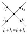
Kirchoff's Node Rule is important to RC Circuits because finding the current flow in the different states of an RC Circuit often relies on nodes when the capacitor is in a parallel circuit.

Kirchhoff’s loop rule explains that the sum of changes in potential around any closed loop must be zero.
A Mathematical Model
These three equations are helpful in solving and understanding RC circuit problems

To find the equation for voltage versus time when charging a capacitor through a resistor, you start with rearranging the energy equation and solving for I:

The graph of Voltage vs. Time in a RC Circuit is given by:

A Computational Model
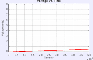
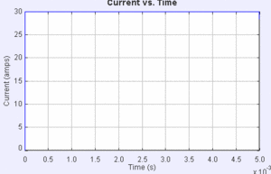
Using a simulation where R and C were equal, the capacitors were charged and then discharged and the two images show the voltage and current of this versus time.
For the gif below, the capacitor is charged and then discharged. This shows the voltage over time. The red line is the voltage and the gray line is the emf. (May have to click image to see gif)

For the gif below, the capacitor is charged and then discharged. This shows the current over time. The blue line is the current. (May have to click image to see gif)

Examples
Simple
In a circuit where time t = RC, the factor [math]\displaystyle{ {e^{\frac{-t}{RC}}} }[/math] has fallen from value [math]\displaystyle{ {e^0} = {1} }[/math] to the value:
e^(-t/RC) = e^1 = 1/e = 1/2.718 = 0.37
Calculate the time constant for the RC circuit with R = 12 ohms and C = 1 farad.
Solution:
[math]\displaystyle{ {RC}= {12*1} = {12 seconds} }[/math]
Middling
Using the information from the problem above:
Show that the power dissipated in the bulb at t=RC is only 14% of the original power?
Solution:
Using [math]\displaystyle{ {IΔV} = {RI^2} }[/math], reduction in current by factor of 0.37 gives a reduction in power by a factor of (0.37)^2 = 0.1369
Difficult
The best example of difficult RC circuit problems come from past exams. Take a look at this RC circuit.

The first step in these problems is to identify all the parts on the circuit and draw in nodes at necessary locations. You want to choose spots for the nodes where the wire splits so you can apply Kirchoff's law and relate the current at these locations.

Once you correctly label the diagram you can begin the problem.
1. Write down the three energy conservation equations for the circuit. Also write down the charge conservation equation for the circuit you would need to determine the current through the bulbs and capacitor. You do not need to solve these equations.
2.Determine the initial current passing through each bulb.
3. Determine the current passing through each bulb for a long time after the switch has been closed.
Connectedness
1. How is this topic connected to something that you are interested in?
- I enjoy listening to music and RC circuits are used in speakers and headphones. They allow the current to be regulated and for the music to to played at the right pitch and volume.
2. How is it connected to your major?
- I'm a Mechanical Engineering major and RC currents are directly related to every job, but in warehouses where heavy machinery and appliances are involved, RC currents are used in parts either at the warehouse or ones that are being assembled. I would be designing the machines not wiring the curcuits, but it is important to understand how the RC circuits are used in order to properly design and implement the machines.
3. Is there an interesting industrial application?
- RC circuits are used as filters for almost all types of electronics. The initial input is taken across the RC circuit and the output is taken across the capacitor. This allows the capacitor in the circuit to be charged to different values and used when the desired one is obtained. It is an easy way to allow multiple energy outputs across a single circuit rather than using a bunch of different circuits.
History
The RC circuits have been in use for a long time. Georg Simon Ohm, was someone who spent alot of time researching RC Circuits and Ohm's Law was founded by him. He did his work from 1830s-1840s and he received recognition, after a long time of being mocked by other scientists. Once his work was recognized and accepted by the scientific community people began to realize the many applications of RC circuits as filters and began to further research and implement them in their own work.
See also
Further reading
External links
http://hyperphysics.phy-astr.gsu.edu/hbase/electric/rcimp.html
http://buphy.bu.edu/~duffy/semester2/c11_RC.html
References
http://www.compadre.org/portal/items/detail.cfm?ID=9986
https://www.pa.msu.edu/courses/1997spring/PHY232/lectures/kirchoff/examples.html


