Resistors and Conductivity: Difference between revisions
| (24 intermediate revisions by the same user not shown) | |||
| Line 3: | Line 3: | ||
==Relevant Equations== | ==Relevant Equations== | ||
The resistance of a material can be calculated in several ways. The most common method relates resistance to the potential difference and the conventional current of the circuit, using the equation | The resistance of a material can be calculated in several ways. The most common method relates resistance to the potential difference and the conventional current of the circuit, using the equation | ||
<math>R = {\frac{ΔV}{I}}</math> | |||
where ΔV is the potential difference across the resistor and I is the conventional current running through the circuit. | |||
Another equation used to quantify resistance relates it to certain properties of the material and geometric properties of the resistor itself: <math>R = {\frac{L}{σA}}</math> where L is the length of the resistor, σ is the conductivity of the material, and A is the cross-sectional area of the resistor. This equation clearly demonstrates that resistivity and conductivity are inverses, as the conductivity constant can be found in the denominator. | The conductivity of a material can be found using the equation | ||
<math>σ = |q|nu = {\frac{\vec{J}}{\vec{E}}}</math> | |||
where |''q''| is the absolute value of the charge on each carrier, ''n'' is the number of charge carriers per m<sup>3</sup>, and ''u'' is the mobility of the charge carriers, '''J''' is the current density (I/A) in A/m<sup>2</sup>, and '''E''' is the electric field due to charges outside the material. | |||
Another equation used to quantify resistance relates it to certain properties of the material and geometric properties of the resistor itself: | |||
<math>R = {\frac{L}{σA}}</math> | |||
where L is the length of the resistor, σ is the conductivity of the material, and A is the cross-sectional area of the resistor. This equation clearly demonstrates that resistivity and conductivity are inverses, as the conductivity constant can be found in the denominator. | |||
==Ohmic vs. Non-Ohmic Resistors== | ==Ohmic vs. Non-Ohmic Resistors== | ||
| Line 29: | Line 41: | ||
[[File:Resistors_in_Series.png|300px|center]] | [[File:Resistors_in_Series.png|300px|center]] | ||
Resistors in series are, in practice, equivalent to a single resistor with the combined resistance of its constituent resistors. In other words, <math>R_{equivalent} = R_1 + R_2 + R_3 + ... + R_n</math> | Resistors in series are, in practice, equivalent to a single resistor with the combined resistance of its constituent resistors. In other words, | ||
<math>R_{equivalent} = R_1 + R_2 + R_3 + ... + R_n</math> | |||
Because R = L/(σA), if every resistor is composed of the same material and has the same cross-sectional area, <math>L_{equivalent} = L_1 + L_2 + L_3 + ... + L_n</math> for ''n'' resistors in series. | for ''n'' resistors in series. | ||
Because R = L/(σA), if every resistor is composed of the same material and has the same cross-sectional area, | |||
<math>L_{equivalent} = L_1 + L_2 + L_3 + ... + L_n</math> | |||
for ''n'' resistors in series. | |||
==Resistors in Parallel== | ==Resistors in Parallel== | ||
| Line 39: | Line 60: | ||
[[File:Resistors_in_Parallel.png|300px|center]] | [[File:Resistors_in_Parallel.png|300px|center]] | ||
Several resistors in parallel are, in practice, equivalent to a single resistor with a resistance that is the reciprocal of the sum of reciprocals of the individual resistances. In other words, <math>{\frac{1}{R_{equivalent}}} = {\frac{1}{R_1}} + {\frac{1}{R_2}} + {\frac{1}{R_3}} + ... + {\frac{1}{R_n}}</math> for ''n'' resistors in parallel. | Several resistors in parallel are, in practice, equivalent to a single resistor with a resistance that is the reciprocal of the sum of reciprocals of the individual resistances. In other words, | ||
<math>{\frac{1}{R_{equivalent}}} = {\frac{1}{R_1}} + {\frac{1}{R_2}} + {\frac{1}{R_3}} + ... + {\frac{1}{R_n}}</math> | |||
for ''n'' resistors in parallel. | |||
Because 1/R = (σA)/L, if every resistor is composed of the same material and has the same length, | |||
<math>A_{equivalent} = A_1 + A_2 + A_3 + ... + A_n</math> | |||
for ''n'' resistors in parallel. | |||
==Examples== | ==Examples== | ||
| Line 48: | Line 78: | ||
[[File:Resistors_in_Series_Example.gif|350px|left]] Because the circuit at left has no branches, the resistors can be considered in series. As such, the values of the resistance of the individual resistors can be summed to find the equivalent resistance. Thus, | [[File:Resistors_in_Series_Example.gif|350px|left]] Because the circuit at left has no branches, the resistors can be considered in series. As such, the values of the resistance of the individual resistors can be summed to find the equivalent resistance. Thus, | ||
<math>R_{equivalent} = R_1 + R_2 + R_3 + R_4</math> | <math>R_{equivalent} = R_1 + R_2 + R_3 + R_4</math> | ||
<math>R_{equivalent} = 65 \ Ω + 84 \ Ω + 73 \ Ω + 10 \ Ω</math> | <math>R_{equivalent} = 65 \ Ω + 84 \ Ω + 73 \ Ω + 10 \ Ω</math> | ||
<math>R_{equivalent} = 232 \ Ω</math> | <math>R_{equivalent} = 232 \ Ω</math> | ||
Using this equivalent resistance and the given voltage (25 V), it is possible to find the value of the current running through the circuit after passing through the resistors. | Using this equivalent resistance and the given voltage (25 V), it is possible to find the value of the current running through the circuit after passing through the resistors. | ||
<math>I = {\frac{ΔV}{R_{equivalent}}} = {\frac{25 \ V}{232 \ Ω}} \approx 0.108 \ A</math> | <math>I = {\frac{ΔV}{R_{equivalent}}} = {\frac{25 \ V}{232 \ Ω}} \approx 0.108 \ A</math> | ||
| Line 58: | Line 93: | ||
[[File:Resistors_in_Parallel_Example.gif|350 px|right]] Because the circuit at right has several possible paths of current, the resistors can be considered in parallel. | [[File:Resistors_in_Parallel_Example.gif|350 px|right]] Because the circuit at right has several possible paths of current, the resistors can be considered in parallel. | ||
As a result, <math>{\frac{1}{R_{equivalent}}} = {\frac{1}{R_1}} + {\frac{1}{R_2}} + {\frac{1}{R_3}} + {\frac{1}{R_4}}</math> | As a result, | ||
<math>{\frac{1}{R_{equivalent}}} = {\frac{1}{R_1}} + {\frac{1}{R_2}} + {\frac{1}{R_3}} + {\frac{1}{R_4}}</math> | |||
<math>{\frac{1}{R_{equivalent}}} = {\frac{1}{10 \ Ω}} + {\frac{1}{20 \ Ω}} + {\frac{1}{30 \ Ω}} + {\frac{1}{40 \ Ω}}</math> | <math>{\frac{1}{R_{equivalent}}} = {\frac{1}{10 \ Ω}} + {\frac{1}{20 \ Ω}} + {\frac{1}{30 \ Ω}} + {\frac{1}{40 \ Ω}}</math> | ||
<math>{\frac{1}{R_{equivalent}}} = {\frac{25}{120}} \ Ω</math> | <math>{\frac{1}{R_{equivalent}}} = {\frac{25}{120}} \ Ω</math> | ||
<math>R_{equivalent} = 4.8 \ Ω</math> | <math>R_{equivalent} = 4.8 \ Ω</math> | ||
The voltage is again provided, and so it is possible to determine the total current I<sub>T</sub> using ΔV and R<sub>equivalent</sub>: | The voltage is again provided, and so it is possible to determine the total current I<sub>T</sub> using ΔV and R<sub>equivalent</sub>: | ||
<math>I_T = {\frac{ΔV}{R_{equivalent}}} = {\frac{24 \ V}{4.8 \ Ω}} = 5 \ A</math> | <math>I_T = {\frac{ΔV}{R_{equivalent}}} = {\frac{24 \ V}{4.8 \ Ω}} = 5 \ A</math> | ||
| Line 86: | Line 128: | ||
*[[Components]] | *[[Components]] | ||
*[[Steady State]] | *[[Steady State]] | ||
*[[Non Steady State]] | |||
*[[Node Rule]] | |||
*[[Loop Rule]] | |||
*[[Power in a circuit]] | |||
*[[Current]] | |||
*[[Georg Ohm]] | |||
==Further Reading== | |||
*[http://www.resistorguide.com/e-book/ The Resistor Guide E-book] | |||
*[http://www.barnesandnoble.com/w/resistor-theory-and-technology-felix-zandman/1101658170?ean=9781891121128 Resistor Theory and Technology, Ed. 1] | |||
*[http://www.amazon.com/The-Resistor-Handbook-Cletus-Kaiser/dp/0962852554 The Resistor Handbook] | |||
== | ==References== | ||
#http://components.about.com/od/Components/a/Resistor-Applications.htm | |||
#http://www.qrg.northwestern.edu/projects/vss/docs/thermal/3-whats-a-resistor.html | |||
#http://www.resistorguide.com/books/ | |||
#http://www.electronics-tutorials.ws/resistor/res50.gif?81223b | |||
#http://www.ceb.cam.ac.uk/data/images/groups/CREST/Teaching/impedence/series2.gif | |||
#https://upload.wikimedia.org/wikipedia/commons/thumb/e/ee/Resistor_symbol_America.svg/2000px-Resistor_symbol_America.svg.png | |||
Created by Kevin Jones, 26 November 2015 | |||
[[Category:Simple Circuits]] | [[Category:Simple Circuits]] | ||
Latest revision as of 19:02, 30 November 2015
A resistor is a component of a circuit that acts to reduce both the flow of current and the voltage levels within the circuit. When current runs through a resistor, the energy stored within particles is converted to another form of energy, typically indicated by the emission of light or heat. Conductivity is a property of a given material that refers to the material's ability to transmit electricity. Conductivity and resistivity are opposites; that is, the higher the conductivity of a material, the less resistance it offers to the flow of current.
Relevant Equations
The resistance of a material can be calculated in several ways. The most common method relates resistance to the potential difference and the conventional current of the circuit, using the equation
[math]\displaystyle{ R = {\frac{ΔV}{I}} }[/math]
where ΔV is the potential difference across the resistor and I is the conventional current running through the circuit.
The conductivity of a material can be found using the equation
[math]\displaystyle{ σ = |q|nu = {\frac{\vec{J}}{\vec{E}}} }[/math]
where |q| is the absolute value of the charge on each carrier, n is the number of charge carriers per m3, and u is the mobility of the charge carriers, J is the current density (I/A) in A/m2, and E is the electric field due to charges outside the material.
Another equation used to quantify resistance relates it to certain properties of the material and geometric properties of the resistor itself:
[math]\displaystyle{ R = {\frac{L}{σA}} }[/math]
where L is the length of the resistor, σ is the conductivity of the material, and A is the cross-sectional area of the resistor. This equation clearly demonstrates that resistivity and conductivity are inverses, as the conductivity constant can be found in the denominator.
Ohmic vs. Non-Ohmic Resistors
Based on the equations above, it is clear that both conductivity and resistance are dependent on the mobility of the charge carriers, and so these values may vary as the current through an object changes. When the conductivity of a material is nearly constant, independent of the amount of current flowing through the resistor, we consider the material and resistor "ohmic." No matter is truly ohmic, as conductivity depends to some extent on temperature, and higher currents often lead to higher temperatures. Materials are generally considered ohmic, however, if the temperature change is minimal.
Symbol and Units
The conventional symbol for a resistor used in electrical circuit diagrams is shown below.
The unit of resistance is the ohm (Ω), and the unit for conductivity is the Siemen per meter (S/m).
Resistors in Series
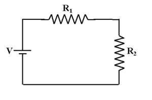
When ohmic resistors are connected along a single path with no branches, as in the figure below, they are said to be in series.

Resistors in series are, in practice, equivalent to a single resistor with the combined resistance of its constituent resistors. In other words,
[math]\displaystyle{ R_{equivalent} = R_1 + R_2 + R_3 + ... + R_n }[/math]
for n resistors in series.
Because R = L/(σA), if every resistor is composed of the same material and has the same cross-sectional area,
[math]\displaystyle{ L_{equivalent} = L_1 + L_2 + L_3 + ... + L_n }[/math]
for n resistors in series.
Resistors in Parallel
When ohmic resistors are not connected in series, they can be connected in parallel (as in the figure below), creating several branches within a circuit.

Several resistors in parallel are, in practice, equivalent to a single resistor with a resistance that is the reciprocal of the sum of reciprocals of the individual resistances. In other words,
[math]\displaystyle{ {\frac{1}{R_{equivalent}}} = {\frac{1}{R_1}} + {\frac{1}{R_2}} + {\frac{1}{R_3}} + ... + {\frac{1}{R_n}} }[/math]
for n resistors in parallel.
Because 1/R = (σA)/L, if every resistor is composed of the same material and has the same length,
[math]\displaystyle{ A_{equivalent} = A_1 + A_2 + A_3 + ... + A_n }[/math]
for n resistors in parallel.
Examples
In Series

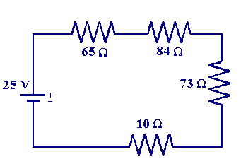
Because the circuit at left has no branches, the resistors can be considered in series. As such, the values of the resistance of the individual resistors can be summed to find the equivalent resistance. Thus,
[math]\displaystyle{ R_{equivalent} = R_1 + R_2 + R_3 + R_4 }[/math]
[math]\displaystyle{ R_{equivalent} = 65 \ Ω + 84 \ Ω + 73 \ Ω + 10 \ Ω }[/math]
[math]\displaystyle{ R_{equivalent} = 232 \ Ω }[/math]
Using this equivalent resistance and the given voltage (25 V), it is possible to find the value of the current running through the circuit after passing through the resistors.
[math]\displaystyle{ I = {\frac{ΔV}{R_{equivalent}}} = {\frac{25 \ V}{232 \ Ω}} \approx 0.108 \ A }[/math]
In Parallel

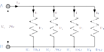
Because the circuit at right has several possible paths of current, the resistors can be considered in parallel.
As a result,
[math]\displaystyle{ {\frac{1}{R_{equivalent}}} = {\frac{1}{R_1}} + {\frac{1}{R_2}} + {\frac{1}{R_3}} + {\frac{1}{R_4}} }[/math]
[math]\displaystyle{ {\frac{1}{R_{equivalent}}} = {\frac{1}{10 \ Ω}} + {\frac{1}{20 \ Ω}} + {\frac{1}{30 \ Ω}} + {\frac{1}{40 \ Ω}} }[/math]
[math]\displaystyle{ {\frac{1}{R_{equivalent}}} = {\frac{25}{120}} \ Ω }[/math]
[math]\displaystyle{ R_{equivalent} = 4.8 \ Ω }[/math]
The voltage is again provided, and so it is possible to determine the total current IT using ΔV and Requivalent:
[math]\displaystyle{ I_T = {\frac{ΔV}{R_{equivalent}}} = {\frac{24 \ V}{4.8 \ Ω}} = 5 \ A }[/math]
The total current IT can also be found by summing the currents I1, I2, I3, and I4 running through each branch. The values of these currents can be obtained using the given voltage and the individual resistances within each branch.
Applications
Light Bulbs
One of the most common applications of the concept of resistance is the incandescent light bulb. In such a light bulb, electricity is forced through a region of tungsten, which acts as a resistor. The energy in the particles is emitted as heat and light.
Heaters
Another instance of the use of resistors in real life is heating. Heat is produced by the interaction of electrons as they flow through the resistor, essentially generating heat via friction.
Other Examples
Other applications of resistance include polygraph machines, radios, televisions, circuit boards, USB drives, and toasters. Any electronic with a circuit board, such as a cell phone or laptop, most likely utilizes a resistor of some type.
See also
Further Reading
References
- http://components.about.com/od/Components/a/Resistor-Applications.htm
- http://www.qrg.northwestern.edu/projects/vss/docs/thermal/3-whats-a-resistor.html
- http://www.resistorguide.com/books/
- http://www.electronics-tutorials.ws/resistor/res50.gif?81223b
- http://www.ceb.cam.ac.uk/data/images/groups/CREST/Teaching/impedence/series2.gif
- https://upload.wikimedia.org/wikipedia/commons/thumb/e/ee/Resistor_symbol_America.svg/2000px-Resistor_symbol_America.svg.png
Created by Kevin Jones, 26 November 2015
