Power in a circuit: Difference between revisions
Fishergreen (talk | contribs) |
Fishergreen (talk | contribs) |
||
| (47 intermediate revisions by the same user not shown) | |||
| Line 1: | Line 1: | ||
==The Main Idea== | ==The Main Idea== | ||
Measuring the power in a circuit can provide useful insight into the ability of a circuit to accomplish a given task. In order to understand how to calculate and interpret power in a simple circuit, one must know the mechanical definition and significance of [[Power]]. For this section, we will be using the unit of Watt for power. | Measuring the power in a circuit can provide useful insight into the ability of a circuit to accomplish a given task. In order to understand how to calculate and interpret power in a simple circuit, one must know the mechanical definition and significance of [[Power]]. For this section, we will be using the unit of Watt for power. | ||
It is important to note that the power | It is important to note that the power dissipated throughout parts of a circuit can be represented in several different ways. Most commonly, power in a circuit is expressed in terms of Voltage (E, Emf, Volts), Current (I, Amps), and Resistance (R, Ohms). It is typical to focus a discussion of power dissipated in a circuit around the power that is dissipated by a resistor. The power dissipated by a resistor directly coincides with the amount of energy that the resistor converts into non-electrical energy such as thermal or light energy. | ||
===A Mathematical Model=== | ===A Mathematical Model=== | ||
The power dissipated in a resistor is <math>P=IV</math> or <math> P=I^2R</math> or <math>P=V^2/R</math> | The power dissipated in a resistor is <math>P=IV</math> or <math> P=I^2R</math> or <math>P=V^2/R</math> | ||
===A | ===A Graphical Model=== | ||
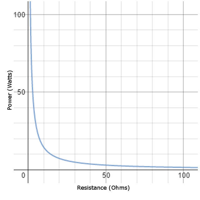
Here is a model of how the power dissipated changes as the resistance in a circuit is modified. This graph is based on a constant voltage of 12 volts. | |||
[[File:Power_in_a_circuit.jpg]] | |||
From the graph, it becomes clear that as resistance increases, the power dissipated by the resistor decreases. | |||
This graph also models how using a potentiometer or variable resistor would effect the power dissipation in a 12 volt circuit. | |||
==Examples== | ==Examples== | ||
===Simple=== | |||
A circuit with a steady voltage of 12 volts has a current of 5 Amps. How much power is dissipated by this resistor? | |||
<math> P=VI=12*5=60</math> Watts | |||
===Middling=== | ===Middling=== | ||
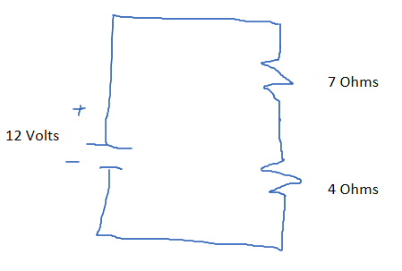
A circuit with a steady voltage of 6 volts contains two resistors in series, one with a resistance of 4 ohms and one with a resistance of 7 ohms. How much power is dissipated by the circuit? | |||
[[File:Circuit_power_problem_2.png]] | |||
First, calculate the overall resistance of the circuit. | |||
<math> R_1+R_2=R_f=7+4=11</math> Ohms | |||
Then we can use one of the above equations to calculate the power dissipation. | |||
<math> P=V^2/R=6^2/12=3</math> Watts | |||
===Difficult=== | ===Difficult=== | ||
A circuit switches from a power supply with 6 volts to a power supply with 12 volts, what is the change in power dissipation if the circuit contains two 4 Ohm resistors wired in parallel? | |||
[[File:Circuit_power_problem_3.png]] | |||
First, we calculate the total resistance of the circuit. Since the resistors are in parallel, we must use the equation: <math>1/R_t=1/R_1+1/R_2</math> | |||
Therefore... <math>R_t=1/(1/4+1/4)=1/.5=2</math> Ohms | |||
Now, we can calculate the power difference by using the change in voltage and the total resistance. | |||
<math>deltaP=(V_1-V_2)^2/2=(12-6)^2/2=36/2=18</math> Watts | |||
==Connectedness== | ==Connectedness== | ||
This topic is extremely important in examining infrastructure related to energy distribution. For example, in power grids, power lines are resistors, and therefore dissipate a certain amount of power. Since resistance is also related to the length of a wire, we can deduce that more power will be dissipated across longer power lines. | This topic is extremely important in examining infrastructure related to energy distribution. For example, in power grids, power lines are resistors, and therefore dissipate a certain amount of power. Since resistance is also related to the length of a wire, we can deduce that more power will be dissipated across longer power lines. | ||
Additionally, it is extremely important to understand the concept of power dissipated by a resistor in the field of Electrical Engineering. For example, knowing how to calculate the power dissipated allows for the calculation of how large a resistor needs to be in order handle the energy dissipated over time through heat. | |||
==History== | ==History== | ||
The discovery of how to calculate the power in a circuit is directly related to the discovery of Ohm's Law which relates voltage to resistance and current. | |||
Ohm's law was discovered by [[Georg_Ohm]]. | |||
The further development of the units for these three properties results in the derivation of the calculation for power dissipation in a circuit. | |||
== See also == | == See also == | ||
[[Ohm's_Law]] | |||
[[Current]] | |||
[[Series Circuits]] | |||
===External links=== | ===External links=== | ||
https://openstaxcollege.org/files/textbook_version/low_res_pdf/9/CollegePhysics-LR.pdf | |||
https://en.wikipedia.org/wiki/Electric_power | |||
==References== | ==References== | ||
| Line 49: | Line 74: | ||
This section contains the the references you used while writing this page | This section contains the the references you used while writing this page | ||
[[Category: | http://mechatronics.mech.northwestern.edu/design_ref/sensors/potentiometers.html | ||
http://hyperphysics.phy-astr.gsu.edu/hbase/electric/elepow.html | |||
https://openstaxcollege.org/files/textbook_version/low_res_pdf/9/CollegePhysics-LR.pdf | |||
http://micro.magnet.fsu.edu/electromag/java/ohmslaw/ | |||
[[Category:Simple_Circuits]] | |||
Latest revision as of 19:16, 30 November 2015
The Main Idea
Measuring the power in a circuit can provide useful insight into the ability of a circuit to accomplish a given task. In order to understand how to calculate and interpret power in a simple circuit, one must know the mechanical definition and significance of Power. For this section, we will be using the unit of Watt for power.
It is important to note that the power dissipated throughout parts of a circuit can be represented in several different ways. Most commonly, power in a circuit is expressed in terms of Voltage (E, Emf, Volts), Current (I, Amps), and Resistance (R, Ohms). It is typical to focus a discussion of power dissipated in a circuit around the power that is dissipated by a resistor. The power dissipated by a resistor directly coincides with the amount of energy that the resistor converts into non-electrical energy such as thermal or light energy.
A Mathematical Model
The power dissipated in a resistor is [math]\displaystyle{ P=IV }[/math] or [math]\displaystyle{ P=I^2R }[/math] or [math]\displaystyle{ P=V^2/R }[/math]
A Graphical Model
Here is a model of how the power dissipated changes as the resistance in a circuit is modified. This graph is based on a constant voltage of 12 volts.
From the graph, it becomes clear that as resistance increases, the power dissipated by the resistor decreases. This graph also models how using a potentiometer or variable resistor would effect the power dissipation in a 12 volt circuit.
Examples
Simple
A circuit with a steady voltage of 12 volts has a current of 5 Amps. How much power is dissipated by this resistor?
[math]\displaystyle{ P=VI=12*5=60 }[/math] Watts
Middling
A circuit with a steady voltage of 6 volts contains two resistors in series, one with a resistance of 4 ohms and one with a resistance of 7 ohms. How much power is dissipated by the circuit?
First, calculate the overall resistance of the circuit.
[math]\displaystyle{ R_1+R_2=R_f=7+4=11 }[/math] Ohms
Then we can use one of the above equations to calculate the power dissipation.
[math]\displaystyle{ P=V^2/R=6^2/12=3 }[/math] Watts
Difficult
A circuit switches from a power supply with 6 volts to a power supply with 12 volts, what is the change in power dissipation if the circuit contains two 4 Ohm resistors wired in parallel?

First, we calculate the total resistance of the circuit. Since the resistors are in parallel, we must use the equation: [math]\displaystyle{ 1/R_t=1/R_1+1/R_2 }[/math]
Therefore... [math]\displaystyle{ R_t=1/(1/4+1/4)=1/.5=2 }[/math] Ohms
Now, we can calculate the power difference by using the change in voltage and the total resistance.
[math]\displaystyle{ deltaP=(V_1-V_2)^2/2=(12-6)^2/2=36/2=18 }[/math] Watts
Connectedness
This topic is extremely important in examining infrastructure related to energy distribution. For example, in power grids, power lines are resistors, and therefore dissipate a certain amount of power. Since resistance is also related to the length of a wire, we can deduce that more power will be dissipated across longer power lines.
Additionally, it is extremely important to understand the concept of power dissipated by a resistor in the field of Electrical Engineering. For example, knowing how to calculate the power dissipated allows for the calculation of how large a resistor needs to be in order handle the energy dissipated over time through heat.
History
The discovery of how to calculate the power in a circuit is directly related to the discovery of Ohm's Law which relates voltage to resistance and current. Ohm's law was discovered by Georg_Ohm. The further development of the units for these three properties results in the derivation of the calculation for power dissipation in a circuit.
See also
External links
https://openstaxcollege.org/files/textbook_version/low_res_pdf/9/CollegePhysics-LR.pdf
https://en.wikipedia.org/wiki/Electric_power
References
This section contains the the references you used while writing this page
http://mechatronics.mech.northwestern.edu/design_ref/sensors/potentiometers.html
http://hyperphysics.phy-astr.gsu.edu/hbase/electric/elepow.html
https://openstaxcollege.org/files/textbook_version/low_res_pdf/9/CollegePhysics-LR.pdf

