Loop Rule: Difference between revisions
(→Simple) |
(→Simple) |
||
| Line 38: | Line 38: | ||
Since we know the <math> emf </math> of the battery we just need to find the potential difference through the resistor. For this we can use the equation of V = IR. | Since we know the <math> emf </math> of the battery we just need to find the potential difference through the resistor. For this we can use the equation of V = IR. | ||
Thus we now have an loop rule equation of <math> emf - IR = 0 </math> | Thus we now have an loop rule equation of <math> emf - IR = 0 </math> | ||
From here it is a relatively simple process to find the current. We can rewrite the loop rule equation as <math> emf = IR </math> and then plug in 5 for the emf and | |||
10 for the resistance, leaving us with I = .5 amperes. | |||
===Middling=== | ===Middling=== | ||
Revision as of 00:08, 4 December 2015
The Loop Rule is a fundamental principle of electric circuits that claims that in any round trip path in a circuit, Electric Potential equals zero.
Loop Rule
The loop rule simply states that in any round trip path in a circuit, Electric Potential equals zero. This principle deals with the conservation of energy within a circuit. Loop Rule and Node Rule are the two fundamental principle of electric circuits and are used to determine the behaviors of electric circuits. This principle is often used to solve for resistance of the light bulbs or other types of resistors or the current passing through these resistors.
A Mathematical Model
A mathematical representation is: [math]\displaystyle{ \Delta {V}_{1} + \Delta {V}_{2} + \space.... = 0 }[/math]
This can also be represented in a circuit as [math]\displaystyle{ emf = \Delta {V}_{1} + \Delta {V}_{2} + \space..... }[/math]
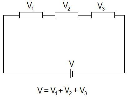
A Visual Model
The total voltage in the circuit is equal to all the individual voltages in the circuit added together.
Another way to think about it is [math]\displaystyle{ \Delta {V} - (\Delta {V}_{1} + \Delta {V}_{2} + \Delta {V}_{3})= 0 }[/math]
Examples
Simple
The circuit shown above consists of a single battery and a single resistor. The resistance of the wires is negligible for this problem.
If the [math]\displaystyle{ emf }[/math] is 5 V and the resistance of the resistor is 10 ohms, what is the current passing through the resistor. Although we can solve this using the V = IR equation for the whole loop, lets examine this problem using the loop rule equation.
The loop rule equation would be [math]\displaystyle{ {V}_{battery} - {V}_{resistor} = 0 }[/math]
Since we know the [math]\displaystyle{ emf }[/math] of the battery we just need to find the potential difference through the resistor. For this we can use the equation of V = IR.
Thus we now have an loop rule equation of [math]\displaystyle{ emf - IR = 0 }[/math] From here it is a relatively simple process to find the current. We can rewrite the loop rule equation as [math]\displaystyle{ emf = IR }[/math] and then plug in 5 for the emf and 10 for the resistance, leaving us with I = .5 amperes.
Middling
The circuit shown above consists of a single battery, whose [math]\displaystyle{ emf }[/math] is 1.3 V, and three wires made of the same material, but having different cross-sectional areas.
Let the length of the thin wires be [math]\displaystyle{ {L}_{thick} }[/math] and the length of the thin wire be [math]\displaystyle{ {L}_{thin} }[/math]
Find a loop rule equation that starts at the negative end of the battery and goes counterclockwise through the circuit.
When beginning this problem, you must notice that the difference in cross-sectional areas affects the electric field in each wire. Because of this we will denote the electric field at D. as [math]\displaystyle{ {E}_{D} }[/math] and the electric field everywhere else as [math]\displaystyle{ {E}_{A} }[/math]. To begin we will go around the circuit clockwise and add up each component. First, we know that the [math]\displaystyle{ emf }[/math] of the battery is 1.3 V. Then, we will add up the potential voltage of each of the wires. Remember that the electric potential of a wire is equal to the electric field * length of the wire. From his we can now find the potential difference of each section of the wires. The electric potential of location A - C is [math]\displaystyle{ {E}_{A} * {L}_{thick} }[/math]. This is the same for the electric potential of location E - G of the wire. For the thin section of the wire, the electric potential is [math]\displaystyle{ {E}_{D} * {L}_{thin} }[/math].
Thus we can find that a loop rule equation is: [math]\displaystyle{ emf - 2 ({E}_{A} * {L}_{thick}) - {E}_{D} * {L}_{thin} = 0 }[/math]
Difficult
History
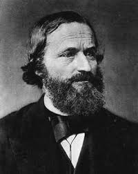
The Loop Rule is formally known as the Kirchhoff Circuit Law, named after Gustav Kirchhoff discovered and defined this fundamental concept of electric circuits. He discovered this during his time as a student at Albertus University of Königsberg in 1845. Kirchoff went on to explore the topics of spectroscopy and black body radiation after his graduation from Albertus. For more in depth information about Gustav Kirchhoff, visit the full wiki page on him: Gustav Kirchhoff

Connectedness
- How is this topic connected to something that you are interested in?
- How is it connected to your major?
- Is there an interesting industrial application?
Since the Loop Rule is a fundamental principle of circuits,
See also
Other Circuit Concepts you can check out :
More Information and External links
Kirchoff's Circuit Laws - Wikipedia
Loop Rule - Boundless.com Textbook
Loop Rule - Doc Physics Video Lecture
References
- https://en.wikipedia.org/wiki/Kirchhoff%27s_circuit_laws#Kirchhoff.27s_voltage_law
- Chabay, Ruth W. Matter and Interactions: Electric and Magnetic Interactions. John Wiley, 2015. Print.
- http://www.ux1.eiu.edu/~cfadd/1360/28DC/Loop.html
Claimed by Bmock7


