Using Capacitors to Measure Fluid Level: Difference between revisions
No edit summary |
|||
| Line 30: | Line 30: | ||
===Middling=== | ===Middling=== | ||
===Difficult=== | ===Difficult=== | ||
== See also == | == See also == | ||
[[Capacitor]] for an overview of capacitors. | |||
Revision as of 23:38, 5 December 2015
Measuring the level of a fluid is useful for a variety of applications, and the technology for the techniques employed in the acquisition of this measurement has progressed far beyond the use of sight glasses and mechanical floats. In fact, a widely used method to measure the amount of fuel in a gas tank is with a device that floats on top of the fuel combined with a sensor, the fuel gauge sending unit, that translates the angle of the float to the amount of fluid in the tank. With this method, the gauge tends to change position with the angle of the car as well as the angle of the float relative to the fluid, so a lot of the time the gauge position can be misleading. A more modern technique of measuring fluid level involves capacitors, and this article will detail the concepts and mathematics behind the relationship with fluid height.
Conceptual Background
Capacitors
For more details, see capacitor.

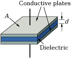
A capacitor consists of two conductors, e.g. conducting plates, separated by some kind of insulator. The insulator--a dielectric--within the gap between the two conductors can be air, plastic, glass, etc. Additionally, the conductors have to be connected to some sort of power supply in order to acquire a buildup of charge on the surface of the conductors.
The magnitude of the electric field within a capacitor is [math]\displaystyle{ \left| \vec{E}_{capacitor} \right| = \frac{Q/A}{\epsilon_{0}} }[/math], where the gap is only occupied by free space. [math]\displaystyle{ Q }[/math] is the charge on a plate and [math]\displaystyle{ A }[/math] is the area of a plate. Additionally, [math]\displaystyle{ \epsilon_{0} }[/math] is the permittivity of free space as detailed here.
Relating Capacitance to Fluid Level
With a dielectric involved, we apply the equation [math]\displaystyle{ \vec{E}_{dielectric} = \frac{\vec{E}_{applied}}{K} }[/math], where [math]\displaystyle{ K }[/math] is the dielectric constant of the material, and get [math]\displaystyle{ \left| \vec{E}_{dielectric} \right| = \frac{Q/A}{K\epsilon_{0}} }[/math]. The capacitance, [math]\displaystyle{ C=\frac{Q}{V} }[/math] (where [math]\displaystyle{ V }[/math] is the voltage) or [math]\displaystyle{ C=\frac{\epsilon_0 A K}{d} }[/math], therefore changes with a varying dielectric constant.
When multiple materials are between the gap, for instance water and air, the overall capacitance would be [math]\displaystyle{ C=\epsilon_0 A (d_{water}+d_{air})(\frac{K_{water}}{d_{water}}+\frac{K_{air}}{d_{air}}) }[/math], where [math]\displaystyle{ d=d_{water}+d_{air} }[/math] and [math]\displaystyle{ K_{air} \approx 1 }[/math]. Thus, correlating capacitance to known levels of water results in a calibration for a sensor using this technique, and the amount of water can be back calculated from the overall capacitance. With more than two dielectrics, the equation can be expanded to include these materials.
A Computational Model
For a simple simulation depicting how changing the amount of dielectric within the gap of a capacitor changes the corresponding electric field, please check out the VPython simulation. The charge on the capacitor as well as the dielectric constants for both dielectrics can be adjusted to visualize how the changes affect the electric field. Notice that the scale factor for the electric field is computed in such a way that the maximum length of the arrow is always the distance between the two plates, so adjusting constants proportionally may result in similar looking arrows (although the electric field will be different). Additionally, you can try changing the color on one of the dielectrics to better visualize the allocation of both within the gap of the capacitor.
A decrease in electric field yields an increase in capacitance, so we can imagine how these two are related. With water and air surrounded by plastic, determining the water level is as simple as measuring the capacitance and solving for the amount of water. In practical applications, these sensors would have to be calibrated and an additional temperature sensor would be needed, because the dielectric constant changes with temperature.
Examples
Be sure to show all steps in your solution and include diagrams whenever possible
Simple
Middling
Difficult
See also
Capacitor for an overview of capacitors.
References
This section contains the the references you used while writing this page