Faraday's Law: Difference between revisions
No edit summary |
|||
| Line 21: | Line 21: | ||
changing the magnetic field. The coil behaves as if it were connected to an emf source. | changing the magnetic field. The coil behaves as if it were connected to an emf source. | ||
Experimentally it is found that the induced emf depends on the rate of change of | Experimentally it is found that the induced emf depends on the rate of change of | ||
magnetic flux through the coil. | magnetic flux through the coil. | ||
Test it out yourself [https://phet.colorado.edu/en/simulation/faradays-law here] | |||
===Mathematical Equation=== | ===Mathematical Equation=== | ||
Revision as of 15:18, 17 April 2016
Claimed by Amber Akbar to edit (Spring 2016)
Faraday's Law of Induction
Faraday's law focuses on how a time-varying magnetic field produces a "curly" non-Coulombic electric field, thereby inducing an emf.
Faraday's Law summarizes the ways voltage can be generated as a result of a time-varying magnetic flux.
Faraday's law is one of four laws in Maxwell's equations. It tells us that in the presence of a time-varying magnetic field or current (which induces a time-varying magnetic field), there is an emf with a magnitude equal to the change in magnetic flux. It serves as a succinct summary of the ways a voltage (or emf) may be generated by a changing magnetic environment. The induced emf in a coil is equal to the negative of the rate of change of magnetic flux times the number of turns in the coil. It involves the interaction of charge with magnetic field.
Faraday's Law Experiment
Faraday showed that no current is registered in the galvanometer when bar magnet is stationary with respect to the loop. However, a current is induced in the loop when a relative motion exists between the bar magnet and the loop. In particular, the galvanometer deflects in one direction as the magnet approaches the loop, and the opposite direction as it moves away.
Faraday’s experiment demonstrates that an electric current is induced in the loop by changing the magnetic field. The coil behaves as if it were connected to an emf source. Experimentally it is found that the induced emf depends on the rate of change of magnetic flux through the coil.
Test it out yourself here
Mathematical Equation
In other words: The emf along a round-trip is equal to the rate of change of the magnetic flux on the area encircled by the path.
Direction: With the thumb of your right hand pointing in the direction of the -dB/dt, your fingers curl around in the direction of Enc.
The meaning of the minus sign: If the thumb of your right hand points in the direction of -dB/dt (that is, the opposite of the direction in which the magnetic field is increasing), your fingers curl around in the direction along which the path integral of electric field is positive. Similarly, the direction of the induced current can be explained using Lenz's Law. Lenz's law states that the induced current from the non-Coulombic electric field is induced in such a way that it produces a magnetic field that opposes the first magnetic field to keep the magnetic flux constant.
Formal Version of Faraday's Law

Problem Solving Tips
To find the direction of the curly electric field, one must find the direction of [math]\displaystyle{ \frac{-dB}{dt} }[/math]. Do this using the change in magnetic field as the basis of finding the [math]\displaystyle{ \frac{-dB}{dt} }[/math].
The easiest way to do this is to imagine the a vector for the initial magnetic field, and a vector for the final magnetic field. Then, draw the change in magnetic field vector, [math]\displaystyle{ \Delta \mathbf{B} }[/math], and then the negative vector of that change in magnetic field gives [math]\displaystyle{ \frac{-dB}{dt} }[/math]:
Pointing the thumb of your right hand in the direction of [math]\displaystyle{ \frac{-dB}{dt} }[/math] allows you to curl your fingers in the direction of [math]\displaystyle{ \mathbf{E_{NC}} }[/math].
In this chapter we have seen that a changing magnetic flux induces an emf:
according to Faraday’s law of induction. For a conductor which forms a closed loop, the emf sets up an induced current I =|ε|/R , where R is the resistance of the loop. To compute the induced current and its direction, we follow the procedure below:
1. For the closed loop of area on a plane, define an area vector A and let it point in the direction of your thumb, for the convenience of applying the right-hand rule later. Compute the magnetic flux through the loop using
Determine the sign of the magnetic flux ![]()
2. Evaluate the rate of change of magnetic flux ![]() . Keep in mind that the change
could be caused by
. Keep in mind that the change
could be caused by
3. The sign of the induced emf is the opposite of that of ![]() . The direction of the
induced current can be found by using Lenz’s law or right hand rule (discussed previously).
. The direction of the
induced current can be found by using Lenz’s law or right hand rule (discussed previously).
More on Faraday's Law
Moving a magnet near a coil is not the only way to induce an emf in the coil. Another way to induce emf in a coil is to bring another coil with a steady current near the first coil, thereby changing the magnetic field (and flux) surrounding the first coil, inducing an emf and a current. Also, rotating a bar magnet (or coil) near a coil produces a time-varying magnetic field in the coil since rotating the magnet changes the magnetic field in the coil. The key to inducing the emf in the second coil is to change the magnetic field around it somehow, either by bringing an object that has its own magnetic field around that coil, or changing the current in that object, changing its magnetic field.
Faraday's law can be used to calculate motional emf as well. A bar on two current-carrying rails connected by a resistor moves along the rails, using magnetic force to induce a current in the wire. There is a magnetic field going into the page. One way to calculate the motional emf is to use the magnetic force, but an easier way is to use Faraday's law.
Faraday's law, using the change in magnetic flux, can be used to find the motional emf, where the changing factor in the magnetic flux is the area of the circuit as the bar moves, while magnetic field is kept constant.
Conceptual Question
Falling Loop
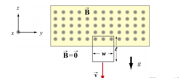
A rectangular loop of wire with mass m, width w, vertical length l, and resistance R falls
out of a magnetic field under the influence of gravity. The magnetic field is uniform and out of the paper ![]() within the area shown and zero outside of that area. At the time shown in the sketch, the loop is exiting the magnetic field at speed
within the area shown and zero outside of that area. At the time shown in the sketch, the loop is exiting the magnetic field at speed ![]()
1) What is the direction of the current flowing in the circuit at the time shown, clockwise or counterclockwise? Why did you pick this direction?
2) Using Faraday's law, find an expression for the magnitude of the emf in this circuit in terms of the quantities given. What is the magnitude of the current flowing in the circuit at the time shown?
3) Besides gravity, what other force acts on the loop in the ±k direction? Give its magnitude and direction in terms of the quantities given.
4) Assume that the loop has reached a “terminal velocity” and is no longer accelerating. What is the magnitude of that terminal velocity in terms of given quantities?
5) Show that at terminal velocity, the rate at which gravity is doing work on the loop is equal to the rate at which energy is being dissipated in the loop through Joule heating.
Examples
Simple

Taken from the Matter & Interactions textbook, variation of P12 (4th ed).
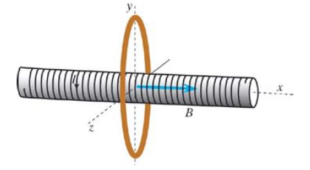
The solenoid radius is 4 cm and the ring radius is 20 cm. B = 0.8 T inside the solenoid and approximately 0 outside the solenoid. What is the magnetic flux through the outer ring?
Solution:
Because the magnetic field outside the solenoid is 0, there is no flux between the ring and solenoid. So the flux in the ring is due to the area of the solenoid, so we use the area of the solenoid to find the flux through the outer ring rather than the area of the ring itself:
[math]\displaystyle{ \phi = BAcos(\theta) }[/math]
[math]\displaystyle{ = (0.8 T)(\pi)(0.04 m)^2cos(0) }[/math]
[math]\displaystyle{ = 4.02 x 10^{-3} T*m^2 }[/math]
Middle

Taken from the Matter & Interactions textbook, variation of P25 (4th ed).
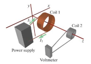
Two coils are aligned with their axes along the z axis, as shown above. Coil 1 is connected to a power supply and has a current flowing clockwise through coil 1, as seen from the location of coil 2. Coil 2 is connected to a voltmeter that gives an emf reading. The distance between the centers of the two coils is x = .12 m. Coil 1 has turns N1 = 500 and radius R1 = 0.05 m. The current through coil 1 changes with time: at t = 0 s, the current through coil 1 is I(0) = 5 A. At t = 0.3 s, the current through coil 1 I(0.3) = 2 A. Coil 2 has turns N2 = 200 and radius R2 = 0.02 m.
(a) What is the direction of [math]\displaystyle{ \frac{-dB}{dt} }[/math]?
(b) What is the direction of the electric field inside the wire of coil 2, at the bottom coil 2?
(c) At t = 0 seconds, what is the magnetic flux through one turn of coil 2?
(d) At t = 0.3 seconds, what is the magnetic flux through one turn of coil 2?
(e) What is the emf in one turn of coil 2 during this time interval?
(f) The voltmeter is connected across all turns of coil 2, so what is the reading on the voltmeter over this time interval?
(g) During this time interval, what is the magnitude of the non-Coulombic electric field inside the wire of coil 2?
Solution:
(a)Because current is decreasing with time, B1, the magnetic field in coil 1, is also decreasing. B1 points in the -z direction. The change in B therefore is +z, and [math]\displaystyle{ \frac{-dB}{dt} }[/math] points in the -z direction.
(b) Enc in coil 2 curls clockwise, when viewed from +z axis, so at the bottom of coil 2, Enc points in the -x direction.
(c) All turns of coil 1 contribute to the magnetic field through coil 2.
[math]\displaystyle{ \phi = BAcos(\theta) }[/math]
[math]\displaystyle{ = (\frac{\mu_0}{4\pi} \frac{2I_1A_1N_1}{(x^2 +R_1^2)^{3/2}}) A_2 }[/math]
[math]\displaystyle{ = \frac{\mu_0}{4\pi} \frac{2(5 A)\pi(0.05 m)^2 (500)}{((0.12 m)^2 +(0.05 m)^2)^{3/2}} * \pi(0.02 m)^2 }[/math]
[math]\displaystyle{ = 2.25 x 10^{-6} T*m^2 }[/math]
(d) Since magnetic flux and I are proportional, and I decreases by a factor of (2/5), the magnetic flux also decreased by (2/5), so [math]\displaystyle{ \phi = 8.98 x 10^{-7} T*m^2 }[/math].
(e) [math]\displaystyle{ |emf| = |\frac{d\phi}{dt}| = \frac{|8.98 x 10^{-7} T*m^2 - 2.25 x 10^{-6} T*m^2|}{0.3 s} }[/math]
[math]\displaystyle{ = 4.49 x 10^{-6} V }[/math]
(f) [math]\displaystyle{ \Delta V = N |emf|_{1 turn} }[/math]
[math]\displaystyle{ = 200(4.49 x 10^{-6} V) = 8.98 x 10^{-4} V }[/math]
(g) [math]\displaystyle{ emf = \int\mathbf{E_{NC}} \cdot d\mathbf{l} }[/math]
Simplifying: [math]\displaystyle{ EL = \Delta{V} }[/math], where [math]\displaystyle{ L = N_2(2\pi(R_2)) }[/math]
[math]\displaystyle{ E = \frac{\Delta{V}}{L} }[/math]
[math]\displaystyle{ = \frac{\Delta{V}}{(N_2)2\pi(R_2)} }[/math]
[math]\displaystyle{ = \frac{8.98 x 10^{-4} V}{(200)2\pi(0.02 m)} }[/math]
[math]\displaystyle{ = 8.98 x 10^{-4} \frac{V}{m} }[/math]
History
Michael Faraday was an English physicist working in the early 1800's. He worked with another scientist named Sir Humphrey Davy. Faraday's big discovery happened in 1831 when he found that when you change a magnetic field, you can create an electric current. He did a lot of other work with electricity such as making generators and experimenting with electrochemistry and electrolysis.
Faraday's experiments started with magnetic fields that stayed the same. That setup did not induce current. It was only when he started to change the magnetic fields that the current and voltage were induced (created). He discovered that the changes in the magnetic field and the size of the field were related to the amount of current created. Scientists also use the term magnetic flux. Magnetic flux is a value that is the strength of the magnetic field multiplied by the surface area of the device.
See also
To fully understand this topic, you need to have an understanding on Maxwell's equations and Lenz's Law.
Further reading
Maxwell, James Clerk (1881), A treatise on electricity and magnetism, Vol. II, Chapter III, §530, p. 178. Oxford, UK: Clarendon Press. ISBN 0-486-60637-6.
Kohlrausch, Friedrich (2005), The Fundamental Laws of Electrolytic Conduction: Memoirs by Faraday, Hittorf and F. Kohlrausch. ISBN: 9781297986291
External links
Faraday's Law Video Explanation: https://www.youtube.com/watch?v=fJjVxR2fynk
Faraday's Law Simulation: https://phet.colorado.edu/en/simulation/faradays-law
References
Encyclopedia.com: http://www.encyclopedia.com/topic/Faradays_law.aspx
Wikipedia (Electromagnetic Induction): http://en.wikipedia.org/wiki/Electromagnetic_induction
Encyclopædia Britannica (Faraday's Law of Induction): http://www.britannica.com/EBchecked/topic/201744/Faradays-law-of-induction
Motional EMF picture: http://web.mit.edu/8.02t/www/materials/StudyGuide/guide10.pdf


