Parallel Circuits: Difference between revisions
No edit summary |
No edit summary |
||
| Line 2: | Line 2: | ||
==The Main Idea== | ==The Main Idea== | ||
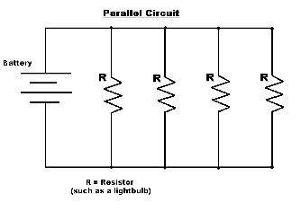
[[Image: | [[Image:Pc1.png|right|thumb|An simple parallel circuit. R1 and R2 lie on different branches of the circuit.]] | ||
Components of a circuit can be connected in two main ways, in series or in parallel. This page focuses on components connected in ''parallel'', which means that the components are connected such that the same voltage is applied to each component. A '''parallel circuit''' is a circuit that is connected entirely in parallel. Each component in a parallel circuit occupies its own ''branch'', or path in the circuit, and these branches are connected at locations called ''nodes''. Thus a charge passing through the circuit has multiple possible paths that it can take when it reaches a node. This property is the reason why adding an additional resistor in a parallel circuit results in a decreased total resistance of the circuit (since there is an additional path that the charges can follow). Likewise, if a path is removed, or if the circuit is broken in a single path, more charge is forced to flow through the remaining paths, and the total resistance increases. | Components of a circuit can be connected in two main ways, in series or in parallel. This page focuses on components connected in ''parallel'', which means that the components are connected such that the same voltage is applied to each component. A '''parallel circuit''' is a circuit that is connected entirely in parallel. Each component in a parallel circuit occupies its own ''branch'', or path in the circuit, and these branches are connected at locations called ''nodes''. Thus a charge passing through the circuit has multiple possible paths that it can take when it reaches a node. This property is the reason why adding an additional resistor in a parallel circuit results in a decreased total resistance of the circuit (since there is an additional path that the charges can follow). Likewise, if a path is removed, or if the circuit is broken in a single path, more charge is forced to flow through the remaining paths, and the total resistance increases. | ||
Revision as of 16:51, 29 November 2017
Claimed by Alex Oshin (Fall 2017)
The Main Idea

Components of a circuit can be connected in two main ways, in series or in parallel. This page focuses on components connected in parallel, which means that the components are connected such that the same voltage is applied to each component. A parallel circuit is a circuit that is connected entirely in parallel. Each component in a parallel circuit occupies its own branch, or path in the circuit, and these branches are connected at locations called nodes. Thus a charge passing through the circuit has multiple possible paths that it can take when it reaches a node. This property is the reason why adding an additional resistor in a parallel circuit results in a decreased total resistance of the circuit (since there is an additional path that the charges can follow). Likewise, if a path is removed, or if the circuit is broken in a single path, more charge is forced to flow through the remaining paths, and the total resistance increases.
A Mathematical Model
- [math]\displaystyle{ V=IR }[/math]
Using the basic Ohm's law we could determine the voltage, resistance, and current throughout a circuit.
- [math]\displaystyle{ \frac{1}{R}_{Total}=\frac{1}{R_1}+\frac{1}{R_2}+\frac{1}{R_3}+...\frac{1}{R_N} }[/math]
When calculating the total Reisistance in a parallel circuit, we need to know the basic principle:
More resistor in parallel circuit, less resistance.
So, we need to find the sum of reciprocals of individual resistors to derive the total resistor.
- [math]\displaystyle{ V_{Total}=V_1=V_2=V_3...=V_N }[/math]
In a parallel circuit, potential difference through out the circuit is equal everywhere.
- [math]\displaystyle{ I_{Total}=I_1+I_2+I_3+...I_N }[/math]
In a parallel circuit, the total amount of current outside the individual branch equals to the sum of individual branches in the circuit. Thus, the individual current in each branch depends on the resistor in the branch.
- [math]\displaystyle{ I_n=I_{Total}\frac{R_{Total}}{R_n} }[/math]
Current Divider Law Since the current running through each branch of the circuit is dependent on the impedance of that branch, the current divider law can be used to determine the magnitude the current through each individual branch.
So if we want to find out the current in [math]\displaystyle{ R_1 }[/math]
- [math]\displaystyle{ I_1=I_{Total}\frac{R_{Total}}{R_1} }[/math]
A Computational Model
This is a simple way to represent a Parallel Circuit. The schematic version is very useful when we want to compute the values, and understand the concept. [math]\displaystyle{ R }[/math] represents a resistor and the [math]\displaystyle{ Battery }[/math] represents the total [math]\displaystyle{ emf }[/math] in the circuit.
This diagram is the actual Parallel Circuit we could see in real life. The actual battery could represent the total emf in the previous schematic sketch, and the light bulb would act as a resistor from the previous parallel circuit.
Examples
These are practical examples we could solve through the formula, and the concept we've learned through this Wiki Page.
Simple
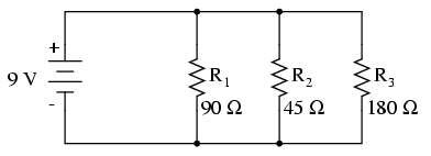
Calculate the total resistance of this parallel circuit.
Solution
- [math]\displaystyle{ \frac{1}{R}_{Total}=\frac{1}{R_1}+\frac{1}{R_2}+\frac{1}{R_3} }[/math]
Using this formula we could derive the total resistance of a parallel circuit.
Plugging in 90 for [math]\displaystyle{ R_1 }[/math], 45 for [math]\displaystyle{ R_2 }[/math], and 180 for [math]\displaystyle{ R_3 }[/math], we get
- [math]\displaystyle{ {R}_{Total}=25.7143 Ω }[/math]
Middling
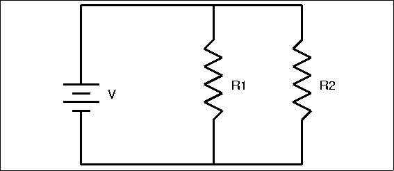
Calculate the current running through [math]\displaystyle{ R_1 }[/math].
Total current running through the circuit is 5 ampere. [math]\displaystyle{ R_1 }[/math]= 4 ohm, and [math]\displaystyle{ R_2 }[/math]= 6 ohm
Solution
In order to find out the current running through [math]\displaystyle{ R_1 }[/math], we can use the current divider law. First calculate the total resistance.
- [math]\displaystyle{ \frac{1}{R}_{Total}=\frac{1}{R_1}+\frac{1}{R_2} }[/math]
Rearranging this formula we get
- [math]\displaystyle{ {R}_{Total}=\frac{R_1R_2}{R_1+R_2}=2.4 Ω }[/math]
Now plug in all the value to the following equation.
- [math]\displaystyle{ I_{Total}=5A }[/math]
- [math]\displaystyle{ I_1=I_{Total}\frac{R_{Total}}{R_1}=3A }[/math]
Difficult
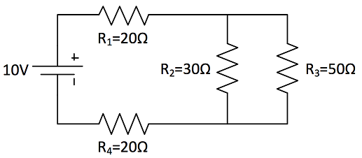
Calculate the current running through [math]\displaystyle{ R_2 }[/math].
Solution
First we have to find out the total resistance of this circuit. Since we have both series and parallel component in the circuit, we have to add all the components to find out the total resistance.
- [math]\displaystyle{ R_{Parallel}=\frac{R_2R_3}{R_2+R_3}=18.75 Ω }[/math]
- [math]\displaystyle{ R_{Total}=R_1+R_{Parallel}+R_4=58.75 Ω }[/math]
Now using the Ohm's law we could determine the total current running through the circuit.
- [math]\displaystyle{ V_{Total}=I_{Total}R_{Total} }[/math]
- [math]\displaystyle{ V_{Total}=10V }[/math]
- [math]\displaystyle{ I_{Total}=\frac{V_{Total}}{R_{Total}} }[/math]
- [math]\displaystyle{ I_{Total}=0.17A }[/math]
We can now use the current divider law to calculate the current running through [math]\displaystyle{ R_2 }[/math].
- [math]\displaystyle{ I_2=I_{Total}\frac{R_{Parallel}}{R_2}=0.10625A }[/math]
To check our answer, calculate the current running through [math]\displaystyle{ R_3 }[/math]
- [math]\displaystyle{ I_3=I_{Total}\frac{R_{Parallel}}{R_3}=0.06375A }[/math]
- [math]\displaystyle{ I_{Total}=I_2+I_3=0.17A }[/math]
Since the total current in a parallel circuit equals to the sum of the current running through each branch, we could verify our answers.
Connectedness
Circuit, including parallel, series, RC, RL... , could be applied to many areas. Circuits are used for many the power sources in the world. In every day's life we encounter using electrical events from turning on lights, using a mp3 player, and so on. Majoring in computer engineering, I have to deal with many circuits, and apply it to the real world. I choose this topic to cover more details about the circuit, and since a lot of students had hard time solving the circuit problem in Test 3. I'm interested in this area, because I can really understand what I can't easily visualize it in real life. By studying circuit, I can understand how power or electricity works, and even computer! In detail, I'm interested in the application of a simple circuit to design a computer. How integrated circuits are used to build a hardware and software.
This website provides some very useful video that shows how simple circuits works in the real world.
History
Integrated Circuit was invented by two inventors name Jack Kilby, and Robert Noyce in the mid 1950s. The work was not done in a corporation. They just came up with the same idea in the same time. Jack Kilby was working for Texas Instrument, whereas Robery Noyce was an research engineer who founded for Semiconductor Corporation. To design a complex computer machine, they needed something more small with more data, and information compared to original transistors, resistors, and capacitors. So they designed an integrated circuit that has many functions within a single chip. It was used to deal with complex matters with minimum cost. From the start of 1960s, many company started to use a chip, replacing the original transistors, and resistors. This integrated circuit is known as one of the most important invention in human kind. I wanted to introduce this specific circuit, because this is what I'm really interested in in my area computer engineering. (Designing the core of the computer)
See also
You could refer to other topics where you can build more idea about the circuits.
First, you should know clearly about the series circuit in order to understand the basic circuit design. In real life we could see a parallel circuit combined with the series circuit, as the example shown in before.
When we thoroughly understand the general idea of a circuit, it's very useful to refer to more complicated circuit as RC cirucit.
These pages would provide some basic information that we could refer to help understand the concept of parallel circuit
Further reading
Introduction to Electric Circuits 9th edition James A. Svoboda Richard C. Dorf
Basic Electric Circuit Theory Issaak D. Mayegoyz W.Lawson
Matter & Interactions Vol. II: Electric and Magnetic Interactions, 4th Edition R. Chabay B Sherwood
External links
References
Including the 3 textbook, I have refereed to the following external sources to create a wikipage.


