Potential Difference in a non-Uniform Field: Difference between revisions
| Line 59: | Line 59: | ||
===Further reading=== | ===Further reading=== | ||
''Applications of Non-Uniform Electric Fields'' | |||
https://pubs.rsc.org/-/content/articlepdf/1966/tf/tf9666203484 | https://pubs.rsc.org/-/content/articlepdf/1966/tf/tf9666203484 | ||
Revision as of 18:30, 24 November 2018
Dalton Lewis Fall 2018
Main Idea
Fields
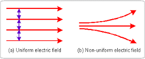
Uniform Field: If the magnitude and direction of an electric field at each and every point in a region is the same, the field in that region is uniform. More specifically, if the electric field vector doesn't vary with position. Non-Uniform Field: If the magnitude and direction of an electric field is different at some point in the region, the field in that region is considered non-uniform.
Electric Field Models: When looking at the graphs below, the Uniform Field has parallel and equal magnitude arrows throughout the region whereas the Non-Uniform Field will have points that go other directions at some point.
Potential Difference
Potential difference is the change in electric potential between a final and initial location. The work done on the charge during this movement will alter its potential energy and because of this change in potential energy, there is a difference in electric potential between these locations.
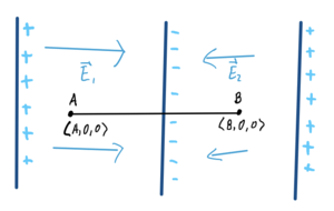
When considering Potential Difference calculated in non-Uniform Fields, the regions should be split into smaller sections of Uniform Fields. For example, the path from the initial location to the final location passes through two regions of uniform, but different fields. In this case, you would split this into two separate calculations for each region and then combine to determine the total potential difference
Mathematical Model
- [math]\displaystyle{ \Delta V }[/math] = [-([math]\displaystyle{ E1_{x} }[/math]●[math]\displaystyle{ \Delta x }[/math] + [math]\displaystyle{ E1_{y} }[/math]●[math]\displaystyle{ \Delta y }[/math] + [math]\displaystyle{ E1_{z} }[/math]●[math]\displaystyle{ \Delta z }[/math])] + [-([math]\displaystyle{ E2_{x} }[/math]●[math]\displaystyle{ \Delta x }[/math] + [math]\displaystyle{ E2_{y} }[/math]●[math]\displaystyle{ \Delta y }[/math] + [math]\displaystyle{ E2_{z} }[/math]●[math]\displaystyle{ \Delta z }[/math]] + ... = -[math]\displaystyle{ \Sigma \vec{E} }[/math]●[math]\displaystyle{ \Delta \vec{l} }[/math]
Computational Model
Examples
Symbolic Example

For this problem, you will need to split the path into two separate parts. In this case, the potential difference will be calculated from location A to B
Create a point in between the boundaries of the two Electric Fields, and use this point to calculate the individual potential differences.
- Calculate Potential Difference from A to the center
- Calculate Potential Difference from the center to B
- Add the values above to get the Potential Difference from A to B
- [math]\displaystyle{ \Delta V_1 }[/math] = -([math]\displaystyle{ E1_{x} }[/math]●[math]\displaystyle{ (Center_x - A_x) }[/math])
- [math]\displaystyle{ \Delta V_2 }[/math] = -([math]\displaystyle{ E1_{x} }[/math]●[math]\displaystyle{ (B_x - Center_x) }[/math])
- [math]\displaystyle{ \Delta V_{total} }[/math] = [math]\displaystyle{ \Delta V_1 }[/math] + [math]\displaystyle{ \Delta V_2 }[/math]
Since all y-values and z-values are zero, they are not considered in the equations above. If they were present (differences in y-values and z-values), then they would be calculated as usual.
Calculated Example
Connectedness
History
See also
Further reading
Applications of Non-Uniform Electric Fields https://pubs.rsc.org/-/content/articlepdf/1966/tf/tf9666203484
External links
https://www.youtube.com/watch?v=j2k6LDafXHI
https://www.youtube.com/watch?v=LG2t1_acgik
https://www.youtube.com/watch?v=qki3pTacXBE
https://www.youtube.com/watch?v=vj2zLThvf-c
