Non Steady State: Difference between revisions
No edit summary |
No edit summary |
||
| Line 1: | Line 1: | ||
by Javier Rodriguez | by Javier Rodriguez | ||
RC circuits in non-steady state are defined by changing charges, currents, and voltages as a function of time. In other words: | RC circuits in non-steady state are defined by changing charges, currents, and voltages as a function of time. In other words: | ||
Revision as of 14:08, 30 November 2015
by Javier Rodriguez
RC circuits in non-steady state are defined by changing charges, currents, and voltages as a function of time. In other words:
Q’(t) ≠ 0
Non-steady state circuits are specifically important when analyzing the charging or discharging a capacitor. Surely, when a capacitor fully charged (Q/C = Emf) or fully discharged (Q=0), the circuit is in steady state — the derivative of charge with respect to time is 0.
Charging a Capacitor
To better understand this, let’s take a look at a simple RC circuit consisting of a battery and a capacitor with a capacitance C.
Assume that the capacitor initially has a charge of Q=0. While the switch remains open, there is no current flowing through the circuit.
The moment the switch closes, the voltage across the capacitor does not instantaneously equal the Emf of the battery. A current initially starts to flow, which allows charges to collect on the plates of the capacitor. At this moment, Q’(t) > 0, and, inger. As time passes, the charges continue to build up, which permits less current to pass through the capacitor — causing the current to decrease under an exponential decay, I’(t) < 0.
Because the voltage drop across a capacitor is directly proportional to charge, this voltage follows the same trend. To find the the exact voltage drop across the plates at any given time t, we can use the following exponential equations:
V(t) = Emf (1 - e-t/RC)
Looking at this equation, we see that as time increases, e-t/RC grows increasingly smaller. After enough time passes, this value will approximate at 0, leaving the voltage at time t to resemble:
V(t) = Emf
At this moment, the capacitor will be fully charged, and no current will flow through the circuit.
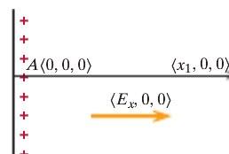
Let's say there is a location B at [math]\displaystyle{ \left(x_1, 0, 0\right) }[/math]. Now in order to find the potential difference between A and C, we need to find the potential difference between A and B and then between B and C.
The potential difference between A and B is [math]\displaystyle{ dV = V_B - V_A = -\left(E_x*\left(x_1 - 0\right) + 0*0 + 0*0\right) = -E_x*x_1 }[/math].
The potential difference between B and C is [math]\displaystyle{ dV = V_C - V_B = -\left(E_x*0 + 0*\left(-y_1 - 0\right) + 0*0\right) = 0 }[/math].
Therefore, the potential difference A and C is [math]\displaystyle{ V_C - V_A = \left(V_C - V_B\right) + \left(V_B - V_A\right) = E_x*x_1 }[/math], which is the same answer that we got when we did not use location B.
Discharging a Capacitor
- How is this topic connected to something that you are interested in?
- How is it connected to your major?
- Is there an interesting industrial application?
History
Put this idea in historical context. Give the reader the Who, What, When, Where, and Why.
See also
Are there related topics or categories in this wiki resource for the curious reader to explore? How does this topic fit into that context?
Further reading
Books, Articles or other print media on this topic
External links
Internet resources on this topic
References
This section contains the the references you used while writing this page

