Faraday's Law - claimed by duql1030: Difference between revisions
No edit summary |
|||
| Line 61: | Line 61: | ||
Faraday's Law is named after Michael Faraday who first published result of the electromagnetic induction experiment. Electromagnetic induction was discovered independently by Michael Faraday in 1831 and Joseph Henry in 1832. He wrapped two wires around opposite sides of an iron ring, and he saw the "wave of electricity" when he turn on the switch. This was due to change in magnetic flux when switch was turned on. Faraday explained this phenomenon using a concept, "lines of force." This was not accepted well because there was no mathematical model to support this explanation. James Maxwell later used Faraday's idea to establish his own quantitative electromagnetic theory. The Maxwell-Faraday equation that is recognized today is Oliver Heaviside's version, which is somewhat altered from the original version. | Faraday's Law is named after Michael Faraday who first published result of the electromagnetic induction experiment. Electromagnetic induction was discovered independently by Michael Faraday in 1831 and Joseph Henry in 1832. He wrapped two wires around opposite sides of an iron ring, and he saw the "wave of electricity" when he turn on the switch. This was due to change in magnetic flux when switch was turned on. Faraday explained this phenomenon using a concept, "lines of force." This was not accepted well because there was no mathematical model to support this explanation. James Maxwell later used Faraday's idea to establish his own quantitative electromagnetic theory. The Maxwell-Faraday equation that is recognized today is Oliver Heaviside's version, which is somewhat altered from the original version. | ||
==References== | ==References== | ||
http://hyperphysics.phy-astr.gsu.edu/hbase/electric/farlaw.html | http://hyperphysics.phy-astr.gsu.edu/hbase/electric/farlaw.html | ||
https://en.wikipedia.org/wiki/Faraday%27s_law_of_induction | |||
Webassign | Webassign | ||
Latest revision as of 22:26, 17 April 2016
Short Description of Topic
The Main Idea
Unlike Coulomb electric field which is produced by charges, Non-Coulomb electric field is electric field along the coil and is associated with changing magnetic field. The non-coulomb electric field is proportional to change in magnetic field and decreases with distance.
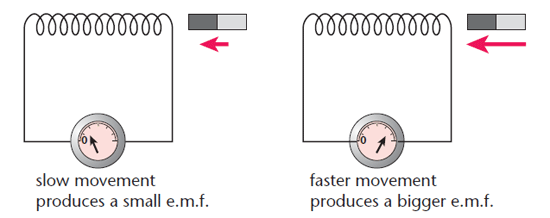
Observing the non coulomb magnetic field, voltage (emf) will be "induced" in a coil by any type of change in the magnetic field on/around the coil of wire. The change of magnetic field can be made by changing distance between magnet(source of the magnetic field) and the coil, rotating the coil relative to the magnetic field, putting coil in and out of magnetic field, and etc.
The direction of the induced current can be decided by first finding the direction of dB/dt. dB/dt is positive if B is increased after a certain interval while it is negative if B decreased after the certain interval. Once the direction of dB/dt is found, the right hand rule is used to find the direction of the current with the thumb pointing -dB/dt.
A Mathematical Model
emf = -(number of turns of the coil)*delta(magnetic flux)/delta(t)
magnetic flux = magnetic field * area
Non-coulomb electric field = induced emf / 2*pi*radius of the coil
Examples
Moving Magnet
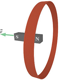
The north pole of a bar magnet points toward a thin circular coil of wire containing 42 turns (see the figure). The magnet is moved away from the coil, so that the flux through one turn inside the coil decreases by 0.1 tesla·m^2 in 0.1 seconds. What is the average emf in the coil during this time interval? Viewed from the right side (opposite the bar magnet), does the current run clockwise or counterclockwise?
dB/dT = .01 (tesla*m^2)/ .01(s)
Therefore, induced emf = N*dB/dT = 42v
The magnetic field is pointing to the right and is decreasing, so -dB/dt is pointing right. Using the right hand rule, the current is running counterclockwise viewed from the right side
Magnetic field due to solenoid
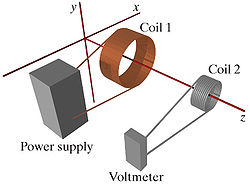
Two coils of wire are aligned with their axes along the z-axis, as shown in the diagram. Coil 1 is connected to a power supply and conventional current flows counter-clockwise through coil 1, as seen from the location of coil 2. Coil 2 is connected to a voltmeter. The distance between the centers of the coils is 0.16 m.
Coil 1 has N1 = 510 turns of wire, and its radius is R1 = 0.09 m. The current through coil 1 is changing with time. At t=0 s, the current through coil 1 is I0 = 16 A. At t=0.4 s, the current through coil 1 is I0.4 = 6 A.
Coil 2 has N2 = 235 turns of wire, and its radius is R2 = 0.03 m.
at t=0s; B0 = (u0*I0*d*L*R1)/(4*pi*(z^2+R1^2)^3/2) * N1 = 1.898e-5 T*m^2
at t=0.4s; B0.4 = (u0*I0.4*d*L*R1)/(4*pi*(z^2+R1^2)^3/2) * N1 = 7.12e-6 T*m^2
induced emf = N2*(B0.4-B0)*pi*R2^2/.4 = .007 V
Non-Coulomb E = emf/(2*pi*R2) = 1.58e-4 V/M
The magnetic field is pointing +z and it is decreasing. -dB/dt is pointing +z, so it can be found that induced current is running counter-clockwise using the right hand rule.
History

Faraday's Law is named after Michael Faraday who first published result of the electromagnetic induction experiment. Electromagnetic induction was discovered independently by Michael Faraday in 1831 and Joseph Henry in 1832. He wrapped two wires around opposite sides of an iron ring, and he saw the "wave of electricity" when he turn on the switch. This was due to change in magnetic flux when switch was turned on. Faraday explained this phenomenon using a concept, "lines of force." This was not accepted well because there was no mathematical model to support this explanation. James Maxwell later used Faraday's idea to establish his own quantitative electromagnetic theory. The Maxwell-Faraday equation that is recognized today is Oliver Heaviside's version, which is somewhat altered from the original version.
References
http://hyperphysics.phy-astr.gsu.edu/hbase/electric/farlaw.html
https://en.wikipedia.org/wiki/Faraday%27s_law_of_induction
Webassign


