Parallel Circuits: Difference between revisions
Okaykeeseok (talk | contribs) |
Okaykeeseok (talk | contribs) |
||
| Line 49: | Line 49: | ||
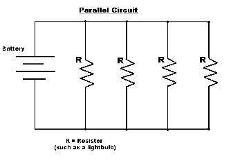
[[File:ParallelCircuit.jpeg]] | [[File:ParallelCircuit.jpeg]] | ||
This is a simple way to represent a Parallel Circuit. The schematic version is very useful when we want to compute the values, and understand the concept. R represents a resistor and the | This is a simple way to represent a Parallel Circuit. The schematic version is very useful when we want to compute the values, and understand the concept. ::<math>R </math> represents a resistor and the <math>Battery</math> represents the total <math>emf</math> in the circuit. | ||
Revision as of 21:42, 2 December 2015
The Main Idea
Parallel Circuit is a circuit that is connected in parallel. All components in parallel circuit are linked to the same set of electric points, and they can create several branches(individual paths) within a circuit. These individual paths provide multiple pathways to the charge, so whenever the charge encounters a branch it would travel to the lower potential. This means adding an additional resistor in a parallel circuit would result in a decreased resistance. In a parallel circuit, the potential difference is identical with each resistor positioned in different branches. If a single circuit is opened(broke), no charge would flow to that path, but other paths will have charges going through them.
In order to understand the parallel circuit, it's critical to know the main difference between series circuit and parallel circuits.
In a series circuit the current is identical through out the circuit, whereas parallel circuit has current, depending on the resistor running through the individual branch. On the other hand, in a series circuit the voltage differs,whereas in parallel circuit the voltage is same everywhere.
A Mathematical Model
- [math]\displaystyle{ V=IR }[/math]
Using the basic Ohm's law we could determine the voltage, resistance, and current throughout the parallel resistor.
- [math]\displaystyle{ \frac{1}{R}_{Total}=\frac{1}{R_1}+\frac{1}{R_2}+\frac{1}{R_3}+...\frac{1}{R_N} }[/math]
When calculating the total Reisistance in a parallel circuit, we need to know the basic principle:
More resistor in parallel circuit, less resistance.
So, we need to find the sum of reciprocals of individual resistors to derive the total resistor.
- [math]\displaystyle{ V_{Total}=V_1=V_2=V_3...=V_N }[/math]
In a parallel circuit, potential difference through out the circuit is equal everywhere.
- [math]\displaystyle{ I_{Total}=I_1+I_2+I_3+...I_N }[/math]
In a parallel circuit, the total amount of current outside the individual branch equals to the sum of individual branches in the circuit. Thus, the individual current in each branch depends on the resistor in the branch.
- [math]\displaystyle{ I_n=I_{Total}\frac{R_{Total}}{R_n} }[/math]
Current Divider Law Since the current running through each branch of the circuit is dependent on the impedance of that branch, the current divider law can be used to determine the magnitude the current through each individual branch.
So if we want to find out the current in [math]\displaystyle{ R_1 }[/math]
- [math]\displaystyle{ I_1=I_{Total}\frac{R_{Total}}{R_1} }[/math]
A Computational Model
This is a simple way to represent a Parallel Circuit. The schematic version is very useful when we want to compute the values, and understand the concept. ::[math]\displaystyle{ R }[/math] represents a resistor and the [math]\displaystyle{ Battery }[/math] represents the total [math]\displaystyle{ emf }[/math] in the circuit.
This diagram is the actual Parallel Circuit we could see in real life. The actual battery could represent the total emf in the previous schematic sketch, and the light bulb would act as a resistor from the previous parallel circuit.
Examples
These are practical examples we could solve through the formula, and the concept we've learned through this Wiki Page.
Simple
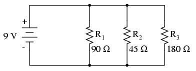
Calculate the total resistance of this parallel circuit.
Solution
- [math]\displaystyle{ \frac{1}{R}_{Total}=\frac{1}{R_1}+\frac{1}{R_2}+\frac{1}{R_3} }[/math]
Using this formula we could derive the total resistance of a parallel circuit. Plugging in 90 for R1, 45 for 42, and 180 for R3, we get
- [math]\displaystyle{ {R}_{Total}=25.7143 ohm }[/math]
Middling
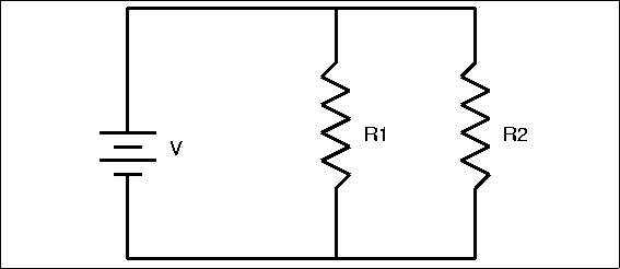
Calculate the current running through R1.
Total current running through the circuit is 5 ampere. R1= 4 ohm, and R2= 6 ohm
Solution
In order to find out the current running through R1, we can use the current divider law. First calculate the total resistance.
- [math]\displaystyle{ \frac{1}{R}_{Total}=\frac{1}{R_1}+\frac{1}{R_2} }[/math]
Rearranging this formula we get
- [math]\displaystyle{ {R}_{Total}=\frac{R_1R_2}{R_1+R_2}=2.4 ohm }[/math]
Now plug in all the value to the current divider law.
- [math]\displaystyle{ I_1=I_{Total}\frac{R_{Total}}{R_1}=3A }[/math]
Difficult
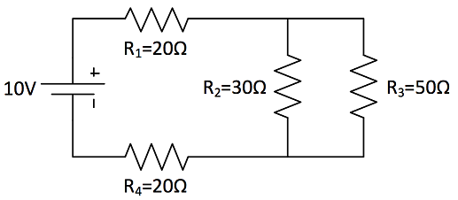
Calculate the current running through R2.
Solution
First we have to find out the total resistance of this circuit. Since we have both series and parallel component in the circuit, we have to add all the components to find out the total resistance.
- [math]\displaystyle{ R_{Parallel}=\frac{R_2R_3}{R_2+R_3}=18.75 ohm }[/math]
- [math]\displaystyle{ R_{Total}=R_1+R_{Parallel}+R_4=58.75 ohm }[/math]
Now using the Ohm's law we could determine the total current running through the circuit.
- [math]\displaystyle{ V_{Total}=I_{Total}R_{Total} }[/math]
- [math]\displaystyle{ V_{Total}=10V }[/math]
- [math]\displaystyle{ I_{Total}=\frac{V_{Total}}{R_{Total}} }[/math]
- [math]\displaystyle{ I_{Total}=0.17A }[/math]
We can now use the current divider law to calculate the current running through R2.
- [math]\displaystyle{ I_2=I_{Total}\frac{R_{Parallel}}{R_2}=0.10625A }[/math]
To check our answer, calculate the current running through R3
- [math]\displaystyle{ I_3=I_{Total}\frac{R_{Parallel}}{R_3}=0.06375A }[/math]
- [math]\displaystyle{ I_{Total}=I_2+I_3=0.17A }[/math]
Since the total current in a parallel circuit equals to the sum of the current running through each branch, we could verify our answers.
Connectedness
- How is this topic connected to something that you are interested in?
- How is it connected to your major?
- Is there an interesting industrial application?
History
Put this idea in historical context. Give the reader the Who, What, When, Where, and Why.
See also
Are there related topics or categories in this wiki resource for the curious reader to explore? How does this topic fit into that context?
Further reading
Books, Articles or other print media on this topic
External links
Internet resources on this topic
References
This section contains the the references you used while writing this page


