Capacitor
Short Description of Topic
This page is all about the Electric Field due to a Point Charge.
The Main Idea
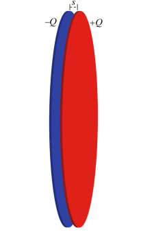
The Main idea is that a capacitor is two uniformly charged disks and it's electric field at the location near the capacitor is sum of electric field by each disk.
Electric Field

Electric Field of two uniformly charged disks: A Capacitor
The Electric Field of a Capacitor can be found by the formula:
Electric field near the center of a two-plate capacitor
[math]\displaystyle{ \ E=\frac{Q/A}{\epsilon_0 } }[/math] One plate has charge [math]\displaystyle{ \ +Q }[/math] and other plate has charge [math]\displaystyle{ \ -Q }[/math]; each plate has area A; Direction is perpendicular to the plates. Assumption: separation between capacitor is very small compared to the area of a plate.
Fringe Field (just outside the plates near center of disk)
[math]\displaystyle{ \ E_{fringe}=\frac{Q/A}{2\epsilon_0 }(\frac{s}{R}) }[/math] [math]\displaystyle{ \ s }[/math] is the separation between plates; [math]\displaystyle{ \ R }[/math] is the radius of plate
The Algorithm
Step 1. Cut up the charge distribution into pieces and find the direction of [math]\displaystyle{ \Delta \vec{E} }[/math] at each location
Approximate electric field of a uniformly charged disk [math]\displaystyle{ \ E=\frac{Q/A}{2\epsilon_0 }[1-\frac{s}{R}] }[/math] or [math]\displaystyle{ \ E=\frac{Q/A}{2\epsilon_0 } }[/math]
At location 2, midpoint between two disks, both disks contribute electric field in the same direction. Therefore, [math]\displaystyle{ \vec{E}_{net} }[/math] is the largest at this location.
At location 1, because negative charged plate is closer, [math]\displaystyle{ \vec{E}_{net} }[/math] is to the right.
At location 3, because positive charged plate is closer, [math]\displaystyle{ \vec{E}_{net} }[/math] is to the left.
Step 2. Find the electric field of each plate
Assumption: Ignore the electric field due to the small charges on the outer surface of the capacitor since it's very small; Assume that separation between capacitor is very small compared to radius or a disk; consider that location 1 and 3 are just near the disk
To make equation valid at all locations, choose origin at the inner face of the left disk so Electric field of the negative charged plate is [math]\displaystyle{ \ E_{-}=\frac{Q/A}{2\epsilon_0 }[1-\frac{s}{R}] }[/math] to the left and Electric field of the positive charged plate is [math]\displaystyle{ \ E_{+}=\frac{Q/A}{2\epsilon_0 }[1-\frac{s-z}{R}] }[/math] to the left
Step 3. Add up
Location 2: Therefore, the location 2, middle of the capacitor, is located z from the negative charged plate and s-z from the positive plate. Since they are in same direction, we simply add them to find [math]\displaystyle{ \vec{E}_{net} }[/math]
[math]\displaystyle{ \vec{E}_{net} = \ E_{-} + \ E_{+} =\frac{Q/A}{2\epsilon_0 }[1-\frac{z}{R}] + \frac{Q/A}{2\epsilon_0 }[1-\frac{s-z}{R}] = \frac{Q/A}{\epsilon_0 }[1-\frac{s/2}{R}] = \frac{Q/A}{\epsilon_0 } }[/math]
Location 1: At location 1, we can see that [math]\displaystyle{ \vec{E}_{net} = \ E_{-} - \ E_{+} = \frac{Q/A}{2\epsilon_0 }[1-\frac{z}{R}] - \frac{Q/A}{2\epsilon_0 }[1-\frac{z+s}{R}] = \frac{Q/A}{2\epsilon_0 }(s/R) }[/math]
Location 3: At location 1, we can see that [math]\displaystyle{ \vec{E}_{net} = \ E_{+} - \ E_{-} = \frac{Q/A}{2\epsilon_0 }[1-\frac{z-s}{R}] - \frac{Q/A}{2\epsilon_0 }[1-\frac{z}{R}] = \frac{Q/A}{2\epsilon_0 }(s/R) }[/math]
Step 4. Check Unit
[math]\displaystyle{ \frac{C/m^2}{N*m^2/C^2} = \frac{N}{C} }[/math]
[math]\displaystyle{ (\frac{C/m^2}{N*m^2/C^2})(m/m) = \frac{N}{C} }[/math]
Examples
For a two-disk capacitor with radius 50cm with gap of 1mm what is the maximum charge that can be placed on the disks without a spark forming? Under these conditions, what is the strength of the fringe field just outside the center of the capacitor? The air breaks down and a spark forms when the electric field in air exceeds 3e6 N/C
First, convert lengths to meter
[math]\displaystyle{ 50cm = 0.5 m }[/math]
[math]\displaystyle{ 1mm = 0.001mm }[/math]
Second, set up the equation [math]\displaystyle{ 3e6 N/C= \frac{Q/A}{\epsilon_0 } }[/math]
Third, solve for Q
[math]\displaystyle{ A= 0.5*0.5*3.14 = 0.785 }[/math]
[math]\displaystyle{ Q= 3e6*8.85e-12*0.785 = 2.01e-5 }[/math]
[math]\displaystyle{ E_(fringe) = \frac{Q/A}{2\epsilon_0 }(s/R) }[/math]
[math]\displaystyle{ \frac{(2.01e-5)/(0.785)}{2\epsilon_0 }(0.001/0.5) = 3000 N/C }[/math]
Connectedness
1. How is this topic connected to something that you are interested in?
Batteries use capacitor to control circuit.
2. How is it connected to your major?
Capacitor and electronic means of Power Factor Correction provide well-known benefits to electric power systems. These benefits include power factor correction, poor power factor penalty utility bill reductions, voltage support, release of system capacity, and reduced system losses. A high power factor signals maximum use of electrical power, while a low power factor leads to purchasing more power to obtain the same load kW, which you pay for in various ways on your utility bill.
3. Is there an interesting industrial application?
A capacitor can store electric energy when it is connected to its charging circuit. And when it is disconnected from its charging circuit, it can dissipate that stored energy, so it can be used like a temporary battery. Capacitors are commonly used in electronic devices to maintain power supply while batteries are being changed.
References
Matter and Interactions, 4th Edition http://www.eaton.com/Eaton/ProductsServices/Electrical/ProductsandServices/PowerQualityandMonitoring/PowerFactorCorrection/index.htm