Lenses
Lenses are found in a huge array of optical instruments, ranging from a simple magnifying glass to the eye to a camera’s zoom lens. Law of refraction is used to explore the properties of lenses and how they form images.
The Main Idea


Index of refraction depends on the wavelength. Thus, light of different wavelengths is bent, or deflected, by different amounts as it passes through a lens. The shape of a lens, either concave or convex, also plays a role in the deflection pattern of light. The images above show that how these two shapes determines the behavior of the light rays. A lens where the middle is thicker than the two ends is called a "convex" lens, through which incoming light rays converge towards the center axis of the lens. A lens where the middle is thinner than the two ends is called a "concave" lens the prisms represent a "diverging" lens, through which incoming light rays diverge away from the center axis. The angle at which light rays converge or diverge is called the deflection angle. Deflection angles for thin lenses will be modeled mathematically in the following section. Thin lenses are lenses where the y position of a light ray does not change very much as the light ray travels through it. In other words, the lens is thick enough to refract light rays, but does not allow dispersion or aberrations.
A Mathematical Model
Law of Refraction
Refraction occurs when light travels through an area of space that has a changing index of refraction. The simplest case of refraction involves a uniform medium with index of refraction [math]\displaystyle{ n_1 }[/math] and another medium with index of refraction [math]\displaystyle{ n_2 }[/math]. The following equation describes the resulting deflection of the light ray:
- [math]\displaystyle{ n_1\sin\theta_1 = n_2\sin\theta_2\ }[/math]
Thin Lens Equation and Magnification

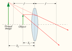
Thin lenses produce focal points on either side that can be modeled using the lensmaker's equation. Thin lenses follow a simple equation that determines the location of the images given a particular focal length ([math]\displaystyle{ f }[/math]) and object distance ([math]\displaystyle{ S_1 }[/math]):
- [math]\displaystyle{ \frac{1}{S_1} + \frac{1}{S_2} = \frac{1}{f} }[/math]
The magnification of a lens is given by
- [math]\displaystyle{ M = - \frac{S_2}{S_1} = \frac{f}{f - S_1} }[/math]
A Computational Model
Examples
Determine the Index of Refraction from Refraction Data

Find the index of refraction for medium 2 in Figure1 (a), assuming medium 1 is air and given the incident angle is 30.0º and the angle of refraction is 22.0º.
Strategy
The index of refraction for air is taken to be 1 in most cases (and up to four significant figures, it is 1.000). Thus [math]\displaystyle{ n_1 = 1.00 }[/math] here. From the given information, [math]\displaystyle{ \theta_1 = 30.0º }[/math] and [math]\displaystyle{ \theta_2 = 22.0º }[/math]. With this information, the only unknown in the lens equation is [math]\displaystyle{ n_2 }[/math], so that it can be used to find this unknown.
Solution
- [math]\displaystyle{ n_1\sin\theta_1 = n_2\sin\theta_2\ }[/math]
Entering known values,[math]\displaystyle{ n_2 = 1.33 }[/math].
Fining the Image of a Light Bulb Filament by Ray Tracing and by the Thin Lens Equations

A clear glass light bulb is placed 0.750 m from a convex lens having a 0.500 m focal length, as shown in Figure2. Use ray tracing to get an approximate location for the image. Then use the thin lens equations to calculate (a) the location of the image and (b) its magnification. Verify that ray tracing and the thin lens equations produce consistent results.
Solution
The ray tracing to scale shows two rays from a point on the bulb’s filament crossing about 1.50 m on the farside of the lens. Thus the image [math]\displaystyle{ d_i }[/math] distance is about 1.50 m. Similarly, the image height based on ray tracing is greater than the object height by about a factor of 2, and the image is inverted. Thus [math]\displaystyle{ m }[/math] is about –2. The minus sign indicates that the image is inverted.
- [math]\displaystyle{ \frac{1}{S_1} + \frac{1}{S_2} = \frac{1}{f} }[/math]
Solving for [math]\displaystyle{ d_i }[/math] from the given known values gives [math]\displaystyle{ d_i = 1.50m }[/math].
The magnification of a lens is given by
- [math]\displaystyle{ M = - \frac{S_2}{S_1} = \frac{f}{f - S_1} }[/math]
Solving for [math]\displaystyle{ m }[/math] gives [math]\displaystyle{ m = -2.00 }[/math]
Image Produced by a Concave Lens
Suppose an object such as a book page is held 7.50 cm from a concave lens of focal length –10.0 cm. Such a lens could be used in eyeglasses to correct pronounced nearsightedness. What magnification is produced?
Connectedness
- How is this topic connected to something that you are interested in?
- How is it connected to your major?
- Is there an interesting industrial application?
History
Optics began with the development of lenses by the ancient Egyptians and Mesopotamians. The earliest known lenses, made from polished crystal, often quartz, date from as early as 700 BC for Assyrian lenses such as the Layard/Nimrud lens.[1] The ancient Romans and Greeks filled glass spheres with water to make lenses. These practical developments were followed by the development of theories of light and vision by ancient Greek and Indian philosophers, and the development of geometrical optics in the Greco-Roman world. The word optics comes from the ancient Greek word Template:Lang, meaning "appearance, look".[2]
Euclid wrote a treatise entitled Optics where he linked vision to geometry, creating geometrical optics. Ptolemy summarised much of Euclid and went on to describe a way to measure the angle of refraction, though he failed to notice the empirical relationship between it and the angle of incidence.


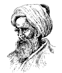
In 984, the Persian mathematician Ibn Sahl wrote the treatise "On burning mirrors and lenses", correctly describing a law of refraction equivalent to Snell's law.He used this law to compute optimum shapes for lenses and curved mirrors. In the early 11th century, Alhazen (Ibn al-Haytham) wrote the Book of Optics (Kitab al-manazir) in which he explored reflection and refraction and proposed a new system for explaining vision and light based on observation and experiment.
See also
Are there related topics or categories in this wiki resource for the curious reader to explore? How does this topic fit into that context?
Further reading
Books, Articles or other print media on this topic
External links
Internet resources on this topic