Metal Detectors
Claimed by Kristie Choe
Short Description of Topic
Introduction to the invention of metal detectors and the physics behind the tool.
The Main Idea
Metal detectors are electromagnetic devices using Faraday's Law used to sense the presence of metal within its reach.
How They Work
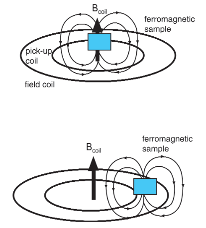
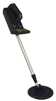
Simple metal detectors have two types of coils: transmitter coils, coils of wire wrapped around the typically circular head at the end of the device's handle and receiver coils. According to Maxwell's equations, as the electricity flows through the transmitter coil and creates an electric field, so too does a magnetic field occur all around it as well. It is necessary for the user to move the detector across the ground so that the magnetic field will move around too. By moving the detector over a metal object, the moving magnetic field around the detector affects the atoms inside the metal, causing the electrons to move in a different manner. Simply put, the detector's moving magnetic field induces electrical activity in the metal object, in turn, now causing another magnetic field to appear around the metal object.
The metal detector is able to detect this new magnetic field because of the receiver coil that is connected to a circuit with a loudspeaker. When the detector moves around the metal object, the induced magnetic field on the object cuts through the coil, causing electricity to flow through the receiver coil, which makes the loudspeaker beep or click. The closer the transmitter coil is to the object, the louder the noise will be from the receiver coil.
A Mathematical Model
Faraday's Law, which states [math]\displaystyle{ \mathcal{E} = -{{d\Phi_B} \over dt} \ }[/math], where [math]\displaystyle{ \mathcal{E} }[/math] is the emf produced from the time-varying magnetic flux ΦB. The flux is given by [math]\displaystyle{ \int_{\Sigma} \mathbf{B} \cdot d\mathbf{A}. }[/math]
The figure below shows a sketch of the effect of a metal object on the magnetic flux when placed in the vicinity of the receiver coil.
Applications of Faraday's Law and Biot-Savart Law in finding magnetic flux and emf:
Emf induced in the pick-up coil: [math]\displaystyle{ {E} = -N_p{{d\Phi} \over dt} \ }[/math]
<math>{Phi} is the magnetic flux in the receiver coil due to the magnetic field produced by the transmitter coil N_p is the number of turns in the receiver coil <\math>
Biot-Savart Law gives magnitude of the magnetic field at the center: B = N_f&mu_0;I(t)/(2R_f)
A Visual Model
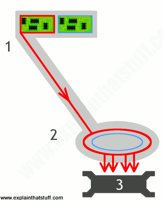
1. The transmitter coil (red circle) is connected to a circuit (red).
2. The transmitter coil induces a magnetic field around it.
3. When the detector moves across a metal object (3), the magnetic field cuts through it.
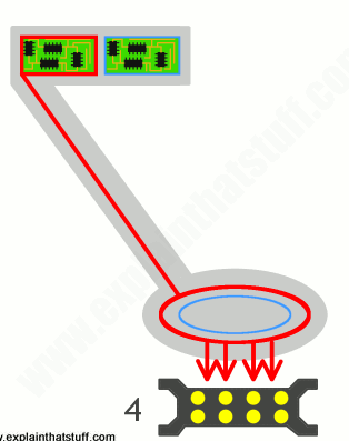
4. The magnetic field induces an electrical current flow inside the metal object (yellow).
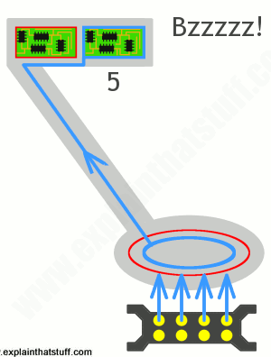
5. This electric field creates a second magnetic field around the metal object (blue arrows), which cuts through the receiver coil (blue circle). This, in turn, causes an electric current to flow through the receiver coil and into the circuit (blue) at the top, making a noise.
Examples of metal detector models
Simple
Middling
Difficult
Connectedness
- How is this topic connected to something that you are interested in?
- How is it connected to your major?
- Is there an interesting industrial application?
History
Put this idea in historical context. Give the reader the Who, What, When, Where, and Why.
See also
Further reading
Books, Articles or other print media on this topic
External links
References
This section contains the the references you used while writing this page
