Current in a RL Circuit
Claimed by Jake Sebring on December 3, 2015 at 11:10 AM
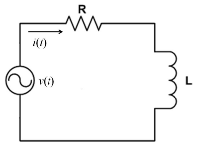
A resistor-inductor circuit is an electric circuit that contains both a resistor, R, and an inductor, L, and is powered by a current source. The energy conservation equation for a RL circuit is typically of the form: ΔV_battery + ΔV_resistor + ΔV_inductor = 0 
Contents [hide] 1 The Main Idea 1.1 A Mathematical Model 1.2 A Computational Model 2 Examples 2.1 Simple 2.2 Middling 2.3 Difficult 3 Connectedness 4 History 5 See also 5.1 Further reading 5.2 External links 6 References The Main Idea[edit] State, in your own words, the main idea for this topic Electric Field of Capacitor
A Mathematical Model[edit] What are the mathematical equations that allow us to model this topic. For example dp⃗ dtsystem=F⃗ net where p is the momentum of the system and F is the net force from the surroundings.
A Computational Model[edit] How do we visualize or predict using this topic. Consider embedding some vpython code here Teach hands-on with GlowScript
Examples[edit] Be sure to show all steps in your solution and include diagrams whenever possible
Simple[edit] Middling[edit] Difficult[edit] Connectedness[edit] How is this topic connected to something that you are interested in? How is it connected to your major? Is there an interesting industrial application? History[edit] Put this idea in historical context. Give the reader the Who, What, When, Where, and Why.
See also[edit] Are there related topics or categories in this wiki resource for the curious reader to explore? How does this topic fit into that context?
Further reading[edit] Books, Articles or other print media on this topic
External links[edit] [1]
References[edit]
This section contains the the references you used while writing this page