Charged Rod
Edits claimed by Ashton Cowart (Spring 2016)
This page provides a brief overview of electric fields created by uniformly charged thin rods. The case of a uniformly charged thin rod is a fundamental example of electric field patterns and calculations within physics. Its implications can be applied to various situations of charged objects.
A Uniformly Charged Thin Rod
In many situations, objects, especially conductors, may have charges spread all over their surface. Sometimes it is necessary to calculate the electric fields of these objects, and this requires a process, known as numerical summation or integration, of dividing an object into many pieces and summing the individual pieces' electric field contributions. But what do these electric field patterns look like? As with point charges, the direction of the field is determined by the sign of the object's charge (positive-points away, negative-points toward) and the size of the field is determined by the observation distance and the magnitude of the object's charge.
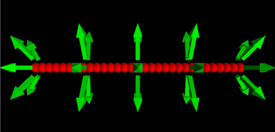
A VPython image of the approximate electric field for a positively charged uniform rod. The field is directed away from the rod at all locations.
The Algorithm
The process of calculating a uniformly charged rod's electric field may seem quite tedious, but breaking the process down into several steps makes the task much easier. Consider a uniformly charged thin rod of length [math]\displaystyle{ L }[/math] and positive charge [math]\displaystyle{ Q }[/math] lying along the x-axis and being observed from above at a point on the y-axis.
First Step
Imagine dividing the rod into a series of very thin slices, each with the same charge [math]\displaystyle{ \Delta Q }[/math]. This charge [math]\displaystyle{ \Delta Q }[/math] is a small part of the overall charge. Imagine it as a point charge. Each slice contributes its own electric field, [math]\displaystyle{ \Delta E }[/math]. Summing all these individual slices of [math]\displaystyle{ E }[/math] gives you the total electric field of the rod. This process is the same as taking an integral, as each thickness approaches 0 and the the number of slices approaches infinity. Note that in this example, the variable that is changing for each slice is its x-coordinate.
Second Step
The second step is to write a mathematical expression for the field [math]\displaystyle{ \Delta E }[/math] contributed by a single slice of the rod. Because we are imagining each slice as a point charge, we use the formula for a point charge. First, determine [math]\displaystyle{ r }[/math], the vector pointing from the source to the observation location. For our example, this is [math]\displaystyle{ r = obs - source = \lt 0,y,0\gt - \lt x,0,0\gt = \lt -x,y,0\gt }[/math]. Now use this to calculate the magnitude and direction of [math]\displaystyle{ r }[/math]. So [math]\displaystyle{ |\vec{r}| = \sqrt{x^2 + (-y)^2} = \sqrt{x^2 + y^2} }[/math] and [math]\displaystyle{ \hat{r} = \frac{\vec{r}}{\hat{r}} = \frac{\lt x,-y,0\gt }{\sqrt{x^2 + y^2}} }[/math]. [math]\displaystyle{ \hat{r} }[/math] is the vector portion of the expression for the field. The scalar portion is [math]\displaystyle{ \frac{1}{4\pi\epsilon_0} \cdot \frac{\Delta Q}{|\vec{r}|^2} }[/math]. Thus the expression for one slice of the rod is: [math]\displaystyle{ \Delta \vec{E} = \frac{1}{4\pi\epsilon_0} \cdot \frac{\Delta Q}{(\sqrt{x^2+y^2})^{3/2}} \cdot \lt x,-y,0\gt }[/math].
Determining [math]\displaystyle{ \Delta Q }[/math] and the integration variable
In the first step, we determined that the changing variable for this rod was its x-coordinate. This should signify that the integration variable is [math]\displaystyle{ dx }[/math]. We need to put this integration variable into our expression for the electric field. More specifically, we need to express [math]\displaystyle{ \Delta Q }[/math] in terms of the integration variable. Recall that the rod is uniformly charged, so the charge on any single slice of it is: [math]\displaystyle{ \Delta Q = (\frac{\Delta x}{L})\cdot Q }[/math]. This quantity can also be expressed in terms of the charge density.
Expression for [math]\displaystyle{ \Delta \vec{E} }[/math]
Substitute the expression for the integration variable into the formula for the electric field of one slice. Separating the equation into separate x and y components, we get [math]\displaystyle{ \Delta \vec{E_x} = \frac{1}{4\pi\epsilon_0} \cdot \frac{Q}{L} \cdot \frac{x}{(\sqrt{x^2+y^2})^{3/2}} \cdot dx }[/math] and [math]\displaystyle{ \Delta \vec{E_y} = \frac{1}{4\pi\epsilon_0} \cdot \frac{Q}{L} \cdot \frac{-y}{(\sqrt{x^2+y^2})^{3/2}} \cdot dx }[/math]. Note that we have replaced [math]\displaystyle{ \Delta x }[/math] with [math]\displaystyle{ dx }[/math] in preparation for integration.
Third Step
The third step is to sum all of our slices. One way is with Numerical summation. Another, more precise method is to integrate. Most of the work of finding the field of a uniformly charged object is setting up this integral. If you have reached the correct expression to integrate, the rest is simple math. The bounds for integration are the coordinates of the start and stop of the rod. In this example the bounds are from [math]\displaystyle{ -L/2 }[/math] to [math]\displaystyle{ +L/2 }[/math]. So the expression is [math]\displaystyle{ \int\limits_{-L/2}^{L/2}\ \frac{1}{4\pi\epsilon_0} \cdot \frac{Q}{L} \cdot \frac{-y}{(\sqrt{x^2+y^2})^{3/2}} \cdot dy. }[/math] Solving this gives the final expression [math]\displaystyle{ E = \frac{1}{4\pi\epsilon_0} \cdot \frac{Q}{r} \cdot \frac{1}{(\sqrt{r^2+ (L/2)^2})} }[/math] Note that the field parallel to the x axis is zero. This can be observed due to the symmetry of the problem.
Approximation Equation
Applications
Brief History
See Also
References
Text Sources
Image Sources
http://compphysed.shodor.org/documents/Info%20materials/WrkGrp-1/VPython_EM/index.html
Work in progress
--Spennell3 (talk) 14:47, 2 December 2015 (EST)
