Current in an LC Circuit
CLAIMED BY: Harrison Cowart 4/11/2016
An LC circuit contains an inductor and a capacitor, and because of the inductor's sluggishness and resistance to change the current, the charge in this circuit can oscillate back and forth forever.
The Main Idea
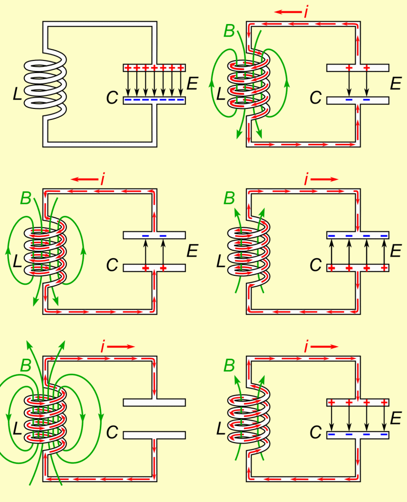
A circuit containing an inductor and a capacitor is called an LC circuit. "L" and "C" are conventional identifiers used in circuit analysis, used for inductors and capacitors respectively. "L" is the symbol used almost exclusively in circuitry as the variable for inductance (measured in henries), or the property of a coil of wire to resist change in current. "C" is the symbol used to denote capacitance (measured in farads), the property of a capacitor, two metal plates separated by a small distance, to store electrical charge. Here is the basic idea behind the process of an LC circuit:
A capacitor is charged initially, and then a switch is closed. This connects the capacitor to the inductor. At first, because of the nature of an inductor, it is difficult for charge on the capacitor to flow through the inductor. This is because the inductor opposes all attempts to change the current. However, since an inductor cannot completely prevent a current from changing, there is more current little by little. This drains the capacitor of its charge.
At the moment the capacitor runs out of charge, there is a current in the inductor, and because inductors are sluggish by nature, the current can't immediately change to zero. Therefore, the system does not come to equilibrium and instead increases the charge in the capacitor. When the capacitor is fully charged, it starts to discharge back through the inductor, and the process repeats. Since the circuit will never reach equilibrium and current never reaches zero, this oscillating process repeats forever. Oscillations could reach a stopping point if there is some resistance, but it may still go through multiple cycles before equilibrium is reached.
A series LC circuit is classified by having an initially charged capacitor and an inductor along the same length of wire. This category of circuitry has special properties that vary from non-inducting circuits. R and RC circuits charge and discharge in an exponential fashion, which prompts shorter time periods between initial current flow and steady-state equilibrium. LC circuits “discharge” in a pattern that resembles the graph of a trigonometric function. This circuit can oscillate continuously if the resistance is small. Accordingly, the connecting wires in an LC circuit are low-resistance thick copper wires.
A Mathematical Model
An LC circuit has an energy conservation rule associated with it. The energy conservation loop rule for an LC circuit is: [math]\displaystyle{ \Delta V_{capacitor} + \Delta V_{inductor} = \frac{1}{C}-L\frac{dI}{dt} = 0 }[/math] where [math]\displaystyle{ Q }[/math] is the charge on the upper plate of the capacitor and [math]\displaystyle{ I }[/math] is the conventional current leaving the upper plate and going through the inductor.
[math]\displaystyle{ dQ/dt }[/math] is the amount of charge flowing off the capacitor every second. This is the same as the current. Because the charge is leaving the capacitor, [math]\displaystyle{ I = -\frac{dQ}{dt} }[/math].
Energy conservation can be re-written as [math]\displaystyle{ \frac{1}{C}Q+L\frac{d^{2}Q}{dt^{2}} = 0 }[/math]
In addition, by substituting Q and its second derivative into the equation, a possible solution of the rewritten energy conservation equation is [math]\displaystyle{ Q = Q_{i}cos(\frac{1}{\sqrt{LC}}t) }[/math]
Therefore, the current is given by: [math]\displaystyle{ I = -\frac{dQ}{dt} = \frac{Q_{i}}{\sqrt{LC}}sin(\frac{1}{\sqrt{LC}}t) }[/math]
A Computational Model
Examples
Use the given circuit and information to solve for the following quantities:
L = 4.0 mH
C = 5.0 μF
Simple
Find the resonant frequency in radians per second and Hertz and the period in seconds:
Middling
Find the initial charge on the fully charged capacitor and the maximum current between oscillations:
Difficult
Connectedness
This topic is connected to RC circuits, which approach equilibrium slowly, as well as RL circuits, which approach steady state current slowly. However, an LC circuit is an example of a circuit that oscillates, where charge moves back and forth forever, and never settles to an equilibrium or steady state.
As an engineer, these circuits can be useful in many areas, particularly to electrical and mechanical engineers. A common applications is tuning radio transmitters and receivers.When we tune a radio to a particular station, the LC circuits are set at a resonance for that particular carrier frequency.
LC circuits can also be applied to voltage magnification and current magnification. LC circuit can additionally be used in induction heating.
History
In 1826, French scientist Felix Savary was the first to discover evidence that a capacitor and an inductor could produce electrical oscillations. In his experiment, he discharged a Leyden jar through a wire wound around an iron needle. He found that sometimes the needle was left magnetized in one direction and other times it was in the opposite direction. He concluded that this was due to a damped oscillating discharge current in the wire, which reversed the magnetization of the needle back and forth until it was too small to have an effect, leaving the needle magnetized in a random direction.
See also
External links
Helpful websites for furthering your understanding of LC circuits, including some mathematical applications: [1] [2]
A helpful video for further information: [3]
References
Matter & Interactions 4th Edition: Electric and Magnetic Interactions
https://en.wikipedia.org/wiki/LC_circuit
http://farside.ph.utexas.edu/teaching/315/Waves/node5.html
http://physics.info/circuits-rlc/


