Transformers (Circuits)
Electricity sent through power lines is transmitted with high voltages through long thick power lines because wires have a resistance that causes power loss at a rate proportional to the current squared. By transmitting at a high voltage, energy loss is minimized. Home appliances however operate at much lower voltages. Something is needed to convert the power to a high current, low voltage power that home appliances can use. This conversion from high voltage to low voltage, and vice versa, is accomplished by a transformer.
Background
Inductance
Currents can be induced (produced) by changing the current through a coil. This is due to the changing magnetic field [math]\displaystyle{ \textstyle (dB/dt) }[/math] produced by varying the current through the coil. We know from the Maxwell-Faraday Law of Maxwell's Equations:
[math]\displaystyle{ |emf| = \oint \overrightarrow{E}_{NC} \cdot d\overrightarrow{l} = \left | \frac{d\phi_{mag}}{dt} \right \vert }[/math]
Or that a changing magnetic field through an area produces a non-Coloumb electric field.
Mathematical Formulae
Before moving on to a discussion of the mathematics of transformers, here are some formulas it will be helpful to recall:
- Magnetic Field Inside a Solenoid: [math]\displaystyle{ B=\frac{\mu_0 N I}{d} }[/math]
- Where [math]\displaystyle{ \textstyle N }[/math] is the number of coils and [math]\displaystyle{ \textstyle d }[/math] is the length of the solenoid.
- Magnitude of self-induced emf: [math]\displaystyle{ \textstyle \left|emf_{ind}\right \vert=L\left|\frac{d I}{d t} \right \vert }[/math]
- Where [math]\displaystyle{ L }[/math] is the proportionality constant called the "inductance" or "self-inductance" which equals [math]\displaystyle{ \textstyle \frac{\mu_0 N^2}{d}\pi R^2 }[/math]
- Expanding this, we get the self-induced emf in a solenoid is: [math]\displaystyle{ \textstyle emf= \frac{\mu_0 N^2}{d}\pi R^2 \frac{d I}{d t} }[/math]
- Finally, remember your units. [math]\displaystyle{ emf }[/math] is measured in volts, self-inductance is [math]\displaystyle{ \textstyle(V•s/A) }[/math] or the "henry" (H), and [math]\displaystyle{ B }[/math] is measured in Tesla (T) or [math]\displaystyle{ \textstyle(\frac{kg}{s^2 A}) }[/math]
How They Work
Conversion from high to low, or low to high voltage can be accomplished using the principles discussed above. Consider a solenoid with [math]\displaystyle{ N_1=100 }[/math] turns around a hollow cylinder of length [math]\displaystyle{ d=.3 m }[/math]. Now wrap [math]\displaystyle{ N_2 = 200 }[/math] turns around this solenoid to form the secondary coil. If an alternating current is run through the primary coil, we get a non-zero [math]\displaystyle{ \textstyle\frac{d I}{d t} }[/math]We can now calculate the potential difference across each coil.
Primary Coil
As stated above, the induced emf in the primary coil is [math]\displaystyle{ L\left|\frac{d I}{d t} \right \vert }[/math]. Expanding this and substituting [math]\displaystyle{ A=\pi R^2 }[/math] for the area, we get a potential difference across the primary coil of [math]\displaystyle{ \textstyle A(\mu_0 N_1^2 /d)dI/dt }[/math].
Secondary Coil
A current is induced in the secondary coil by the changing magnetic field produced by the primary coil. The magnetic field is [math]\displaystyle{ \textstyle B = \mu_0 N_1 I/d }[/math] and it is changing across area [math]\displaystyle{ A }[/math] (which is only the area of the inner coil, not the outer secondary coil. So the emf in one turn of the secondary coil is [math]\displaystyle{ A dB/dt }[/math]. We have [math]\displaystyle{ N_2 }[/math] secondary coils, so the emf is [math]\displaystyle{ N_2 AdB/dt }[/math]. If we expand out our [math]\displaystyle{ dB/dt }[/math] term, we can get the emf across the second coil in a formula similar to the emf across the primary coil: [math]\displaystyle{ emf_{sec} = N_2A(\mu_0N_1/d)dI/dt }[/math].
Voltage Ratio
We now can see that the ratio of the secondary to primary emf is [math]\displaystyle{ emf_{pri}/emf_{sec} }[/math]. This yields:
[math]\displaystyle{ \frac {N_2A(\mu_0N_1/d)dI/dt}{A(\mu_0 N_1^2 /d)dI/dt} }[/math] which cancels and leaves [math]\displaystyle{ \frac {N_2}{N_1} }[/math] or in this case [math]\displaystyle{ \frac{200}{100} }[/math].
This transformer would create a emf 2 times the emf in the primary coil. Because we can't create energy from nothing, power ([math]\displaystyle{ I\Delta V }[/math]) must be conserved; the double voltage in the secondary coil is accompanied by a current of half the strength of the primary coil.
The transformer described above is called a "step-up" transformer because it "ups" the voltage. There are also "step-down" transformers which reduce the voltage and have fewer turns on the secondary coil than primary coil.
Circuits
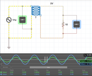
Include here: a gif of 1 to 1 transformer, step up, step down and converting AC back to DC.

See also
- Faraday's Law This will give you a general understanding of Faraday's Law, which is the basis behind transformer technology.
- Inductance A more in depth look at Inductance, a direct consequence of Faraday's Law.
- Gauss's Flux Theorem Changing the flux of a magnetic field around a coil will induce voltage.
- Transformers from a physics standpoint Detail on the material properties and physics of transformers, outside the scope of circuits.
Further reading
Books, Articles or other print media on this topic
References
Chabay, R., & Sherwood, B. (2015). Electric Potential. In Matter & interactions (4th ed., Vol. Two, pp. 917-921). Danvers, Massachusetts: J. Wiley & sons.
iCircuit - Electronic Circuit Simulator and Designer (available for Windows, Mac, and iOS)