Biot-Savart Law for Currents
Claimed by Abigail Ochal Fall 2020
Biot-Savart Law
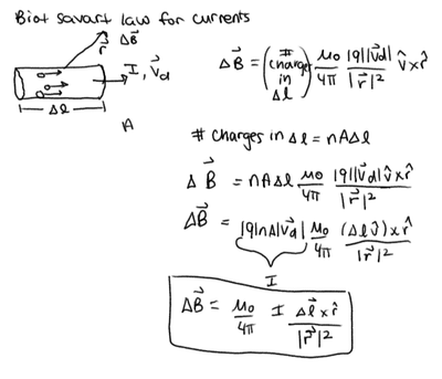
The Biot-Savart Law can be used for more than just single moving charges; a notable application of this law is its ability to calculate the magnetic field for an extremely large number of charges - an example of thousands of charges moving together is within a current carrying wire (current being the amount of charges moving over a specific amount of time).
When using Biot-Savart Law to find the magnetic field of a short wire, we can extend this concept to a variety of different shapes - long current carrying wires, current carrying loops, etc.
- One main point to note is that the application of the Biot-Savart law is specifically for steady state current (current that is not changing over time ----- [math]\displaystyle{ dI/dt = 0 }[/math] )!
A Mathematical Model
First We start off with the original version of the Biot-Savart Law. [math]\displaystyle{ \vec B=\frac{\mu_0}{4 \pi } \frac{q\vec v\times\hat r}{r^2} }[/math], where [math]\displaystyle{ \frac{\mu_0}{4 \pi } = 1 \times 10^{-7}\frac{Tm^2}{Cm/s}, }[/math]
Because we are dealing with a portion of wire [math]\displaystyle{ \mathrm{d}\boldsymbol{\ell} }[/math] long with an Area A containing n moving particles with charge q, we find that the total number of moving charges is equal to |q|(nAv) which is also equal to I, the current in the wire.
[math]\displaystyle{ B = \frac{\mu_0I}{4\pi}\frac{\mathrm{d}\boldsymbol{\ell} \times \mathbf{\hat r}}{r^2}, }[/math]

Because the shape of the current carrying wire can vary from a straight wire to a loop, we must integrate over the region of the wire.
[math]\displaystyle{ \Delta B = \frac{\mu_0I}{4\pi}\int_{\mathrm{wire}}\frac{\mathrm{d}\boldsymbol{\ell} \times \mathbf{\hat r}}{r^2}, }[/math]
The key point is that there are [math]\displaystyle{ nA\Delta l }[/math] electrons in a short length of wire, each moving with average speed [math]\displaystyle{ \vec v }[/math], so that the sum of all the [math]\displaystyle{ q\vec v }[/math] contributions is [math]\displaystyle{ nA \Delta l|q|\vec v = I\Delta l. }[/math]
When applying the Biot-Savart Law to a Long Straight Wire, we follow a set of steps,
Step 1: Cut Up the Distribution into Pieces ([math]\displaystyle{ \Delta l }[/math]) and Draw [math]\displaystyle{ \Delta B }[/math].
Step 2: Write an Expression for the Magnetic Field Due to One Piece.
Step 3: Add Up the Contributions of All the Pieces (each [math]\displaystyle{ \Delta l }[/math] adds together to make the entirety of the length).
Step 4: Check the Result.
Where the Magnetic Field of a Straight Wire is shown by,
[math]\displaystyle{ B = \frac{\mu_0}{4\pi}\frac{LI}{r(r^2 + (L/2)^2)^{1/2}} }[/math] for length [math]\displaystyle{ L }[/math], conventional current [math]\displaystyle{ I }[/math], a perpendicular distance [math]\displaystyle{ r }[/math] from the center of the wire, or, [math]\displaystyle{ B = \frac{\mu_0}{4\pi}\frac{2I}{r} }[/math] if [math]\displaystyle{ L\;\gt \;\gt r. }[/math]
Right Hand Rule

When using the Biot-Savart Law for Currents, it is crucial to understand the direction of the magnetic field created by a current.
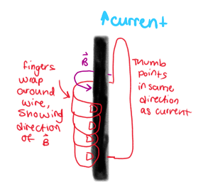
In order to get the direction of the Magnetic Field, as shown in the image on the right, we:
1. Point our thumb in the direction of the current, and
2. automatically curl our fingers around in one direction.
This curling direction is the direction of the magnetic field itself.

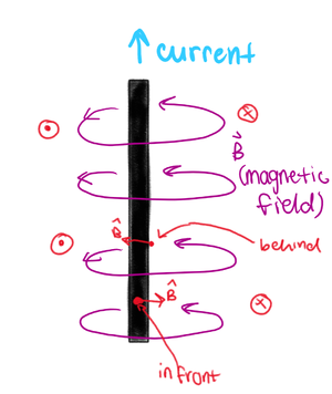
If we are looking at an observation location directly to the left of the wire, then we know the magnetic field is pointing out of the page. If we are looking at an observation location directly to the right of the wire, then the magnetic field is pointing into the page. If the observation location is directly in front of the wire (closest to us), then the magnetic field is pointing to the right. If the observation location is directly behind the wire, then the magnetic field is to the left.
Picking a few different observation locations can help to visualize the circular nature of the magnetic field due to the current in the wire.
Another way to determine the direction of the magnetic field due to the current would be to use cross product of the vector dl and rhat. When dl and rhat are parallel, the magnetic field will be 0.
Long Wire Integration Example

For a long wire of length L positioned along the x axis with current flowing in the positive x direction (as shown by image on right)
First, we start off with our adjusted Biot-Savart Formula for a slice of wire.
[math]\displaystyle{ \Delta B = \frac{\mu_0I}{4\pi}\int_{\mathrm{wire}}\frac{\mathrm{d}\boldsymbol{\ell} \times \mathbf{\hat r}}{r^2}, }[/math]
Second, we must find [math]\displaystyle{ r }[/math], the vector pointing from the source to the observation location. In this case, we will choose an observation location y above the rod.
[math]\displaystyle{ r = obs - source = \lt 0,y,0\gt - \lt x,0,0\gt = \lt -x,y,0\gt }[/math]. which has a magnitude of [math]\displaystyle{ \sqrt(x^2+y^2) }[/math]
We see that [math]\displaystyle{ \hat r = \frac{r}{|r|} }[/math] .
[math]\displaystyle{ \hat r = \frac{\lt -x,y,0\gt }{\sqrt(x^2+y^2))} }[/math]
We then have to express [math]\displaystyle{ \Delta \boldsymbol{\ell} }[/math] in terms of our variable of integration, x. [math]\displaystyle{ \Delta \boldsymbol{\ell} }[/math] = [math]\displaystyle{ \Delta x\lt 1,0,0,\gt }[/math]
Our new equation after substituting our new variables is [math]\displaystyle{ \Delta B = \frac{\mu_0I\Delta x\lt 1,0,0,\gt }{4\pi(x^2+y^2)} \times \frac{\lt -x,y,0\gt }{\sqrt(x^2+y^2))} }[/math]
Finding the cross product of the above vectors gives us a product in the +z direction. [math]\displaystyle{ \Delta B = \frac{\mu_0I\Delta x}{4\pi(x^2+y^2)^(\frac{3}{2})} }[/math]
We are finally ready to integrate. Because we are integrating the entire rod our limits are
[math]\displaystyle{ \int\limits_{-L/2}^{L/2}\ }[/math] [math]\displaystyle{ \int\limits_{-L/2}^{L/2}\ = \frac{\mu_0I\Delta x}{4\pi(x^2+y^2)^(\frac{3}{2})} }[/math]
We find that our final answer is [math]\displaystyle{ B= \frac{\mu_0}{4\pi}\frac{LI}{y\sqrt(y^2+(L/2)^2)}\hat z }[/math]
Current Loop Integration Example
Saved for Elizabeth Clayton 10/7/2020
A Computational Model
The following link shows the magnetic field produced by small segments of wire in a loop individually. For a long straight wire, we see that there is a circular magnetic field surrounding the wire with current. The following link does a stepwise visual of the contributions of each part of the wire at an observation location a distance r from the wire.
We see that along the axis of the wire, each contribution not on the axis is negated due to symmetry and the resulting magnetic field is all along the wire.
Connectedness
In biochemistry, there are lots of instruments that rely on magnets and magnetic fields to gather information about different molecules.
One example is proton nuclear magnetic resonance (H+ NMR), which creates peaks corresponding to hydrogen atoms (protons) on adjacent carbon atoms in organic molecules.
Another example, which is commonly used in medicine, is magnetic resonance imaging (MRI), which takes images using magnets to interact with protons in the body. For more information, go to the "External Links" Section.
History
Jean-Baptiste Biot and Félix Savart worked together to understand current and magnetic fields during the 1820's. Find more information about the history in "External Links"
See also
[Right Hand Rule[1]]
[Direction of magnetic fields[2]] Are there related topics or categories in this wiki resource for the curious reader to explore? How does this topic fit into that context?