Steady State
Claimed Alex Dulisse (Spring 2018)
Imagine a circuit in which the only battery has been disconnected. In such a setup there would be no electric field in the circuit and therefore no moving charges so the circuit would be in static equilibrium. When the battery is reconnected, an electric field will quickly propagate through the circuit and the charges in the circuit will accelerate. After a short time, the charges will move at a constant speed through the circuit and the electric field at each part of the circuit will remain unchanged. This means that at any given moment, all properties of the circuit remain unchanged even though an electric field is acting on the charges. At this time, when the state of the circuit does not change with the passage of time, the circuit is said to be in steady state.

The Main Idea
If a circuit is in steady state the following will be true:
- At each part of the circuit, the drift velocity of charges remains unchanged with time.
- The maximum amount of energy has been stored in capacitors, inductors.
- Excess charge only accumulates on the surface of the wire.
- An unchanging voltage exists between any two points in the system.
Each of these bullets is a different way of saying the same thing, that the state of the circuitry acting on any charges remains unchanged with respect to time. It is important to remember that a circuit being in steady state does not mean that the drift speed is the same every where in the circuit, only that it is unchanging for each specific location in the circuit. Also, a circuit in which there is no current may still be in steady state (such as an RC circuit in which the capacitors are fully charged), as long as there is still a constant electric field in all conductive parts of the circuit.
A Conceptual Understanding
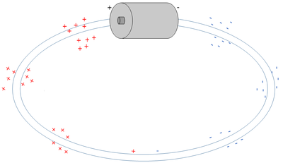
For charges to move through the circuit, there must be an applied electric field that causes the mobile charges to move. Since there cannot be excess charge in the interior of a conductor, the surface charges must be producing the electric field. This electric field must be parallel to the wire because of the properties of a conductor. In a conductor, mobile charges always move to cancel out an electric field, meaning that the only electric field in the circuit must be parallel to the direction of current flow. It is also important to conceptually understand why this electric field eventually reaches steady state. When a battery is first connected to a circuit, the electric field increases in magnitude, the rate at which the charges move through the circuit increases in magnitude too. As charges move through the circuit, there is a drag force in the opposite direction of their motion (similar to friction) known as the resistance of the wire. Since [math]\displaystyle{ I=V/R }[/math], eventually these opposing forces will be equal in magnitude, bringing the circuit to steady state. Once a circuit is described as being in the steady state, there must be a constant electric field in the wire, the electric field has uniform magnitude throughout wire sections with similar cross-sectional area, and the electric field is parallel to the wire at every location along the wire.

Steady State vs. Other States When circuits move from static equilibrium to steady state, they typically do so in a very small amount of time. However, the Non Steady State, or Transient State, which takes place in between, is an important aspect of circuits. When a circuit is in the Non Steady State, over time its state will approach the steady state. After enough time has elapsed, the difference is so slim that the circuit can be considered to be in steady state, even though in theory it never quite reaches steady state. The equations to model Non Steady States are different depending on the type of circuit being analyzed.
The following chart compares common properties of circuits in Static Equilibrium, Steady State, and Non Steady States:
| Static Equilibrium | Steady State | Non Steady State | |
|---|---|---|---|
| [math]\displaystyle{ \bar{v} }[/math] | [math]\displaystyle{ = 0 }[/math] | [math]\displaystyle{ \neq 0 }[/math] | [math]\displaystyle{ \neq 0 }[/math] |
| [math]\displaystyle{ \frac{d\bar{v}}{dt} }[/math] | [math]\displaystyle{ = 0 }[/math] | [math]\displaystyle{ = 0 }[/math] | [math]\displaystyle{ \neq 0 }[/math] |
| [math]\displaystyle{ \sum E_{inside} }[/math] | [math]\displaystyle{ = 0 }[/math] | [math]\displaystyle{ \neq 0 }[/math] | [math]\displaystyle{ \neq 0 }[/math] |
A Mathematical Model
Current
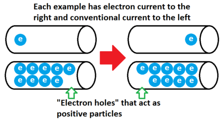
There are two ways to describe current in a circuit, the electron current ([math]\displaystyle{ i }[/math]), and the conventional current ([math]\displaystyle{ I }[/math]). Electron current describes the motion of charges as it actually happens in the circuit: electrons moving through the conductor. Conventional current has the same magnitude and opposite direction as electron current as it describes positive charges moving through a circuit. Although circuits will sometimes act like positive charges are moving through the circuit if there are “electron holes,” it is important to understand that there are not positively charged particles moving through circuits. Even though it is backwards from the physical reality, conventional current is more commonly used because the motion of electrons in circuits was not understood when the first discoveries of electricity were made.
The following formulas can be used to describe electron and conventional current, respectively:
[math]\displaystyle{ i= nA\bar{v} }[/math]
[math]\displaystyle{ I = \left | q \right |nA\bar{v} }[/math]
n = charge density, the number of charged particles per unit volume
A = cross sectional area of the wire
v = drift speed, the speed at which mobile charges move through a section of wire
q = charge of the mobile particles being described (only matters for conventional current)
Keep in mind that drift velocity [math]\displaystyle{ \bar{v}=\mu \left | E_{applied} \right | }[/math]
Where [math]\displaystyle{ \mu }[/math] = electron mobility.
If you have trouble thinking of this conceptually, imagine a pipe carrying water. For a certain amount of water to move through each part of the pipe per unit time, if the pipe is smaller, the water must move faster and for more water to be delivered, either the speed of the water must increase or the size of the pipe must increase.
Kirchoff's Node Rule
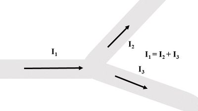
When a wire splits in to two, this junction is referred to as a node. Current flowing through the node must follow the equation [math]\displaystyle{ \Sigma I_{in} = \Sigma I_{out} }[/math]. This is called the “Node Rule.” All this is saying is that exactly what enters the node must exit. In other words, charge dose not disappear or come into existence just because one wire splits in two.

Examples
Simple
Question
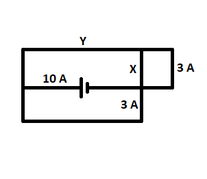
What are the values of X and Y in the following circuit?

Solution
Based on the node rule, 10=3+3+X. Therefore X=4.
Y=3+X, therefore Y=3+4=7
Middling
(Example taken from the OpenStax College Physics Textbook)
Question
Calculate the drift velocity of electrons in a 12-gauge copper wire (which has a diameter of 2.053 mm) carrying a 20.0-A current, given that there is one free electron per copper atom. The density of copper is [math]\displaystyle{ 8.80\times 10^{3} kg/m^3 }[/math].
Solution
First, calculate the density of free electrons in copper. There is one free electron per copper atom. Therefore, is the same as the number of copper atoms per [math]\displaystyle{ m^3 }[/math]. We can now find [math]\displaystyle{ n }[/math] as follows:
[math]\displaystyle{ n= \frac{1e-}{atom}\times \frac{6.02\times10^{23}atoms}{mol}\times \frac{1 mol}{63.54 g} \times \frac{1000 g}{kg} \times \frac{8.80 \times 10^3 kg}{1 m} }[/math]
[math]\displaystyle{ n= 8.342\times 10^{28}e−/m^3 }[/math]
The cross-sectional area of the wire is
[math]\displaystyle{ A= \pi r^2 = \pi(2.053\times0.5\times10^{−3})^2 = 3.3103 \times 10^{–6}m^2 }[/math]
Rearranging [math]\displaystyle{ I= \left | q \right |nA\bar{v} }[/math] to isolate drift velocity gives you:
[math]\displaystyle{ \bar{v}= \frac{I}{n\left |q \right |A} }[/math]
[math]\displaystyle{ \bar{v}= \frac{20.0A}{(8.342\times10^{28}/m^3) (1.60\times10^{-19}C)(3.310\times10^{-6}m^2)} }[/math]
[math]\displaystyle{ \bar{v}= 4.53\times 10^{–4}m/s }[/math]
Difficult
Question
A circuit made of two wires is in the steady state. The battery has an emf of 1.5 V. Both wires are length 25 cm and made of the same material. The thin wire's diameter is 0.25 mm, and the thick wire's diameter is 0.31 mm. There are [math]\displaystyle{ 4\times 10^{28} }[/math] mobile electrons per cubic meter of this material, and the electron mobility of this material is 0.0006 (m/s)/(V/m).
A) If the magnitude of the electric field in the thin wire is 3.5 V/m, what is the electric field in the thick wire?
B) What is the drift velocity in the thin and thick wires?
Solution
Based on the Node Rule, we know that the electric current is equal in both wires:
[math]\displaystyle{ i_{thick}=i_{thin} }[/math]
We also know that [math]\displaystyle{ i= nA\bar{v} = nA \mu E }[/math]. Therefore:
[math]\displaystyle{ nA_{thick} \mu E_{thick} = nA_{thin} \mu E_{thin} }[/math]
When we rearrange this to solve for [math]\displaystyle{ E_{thick} }[/math], the electron mobility ([math]\displaystyle{ \mu }[/math]) and electron density ([math]\displaystyle{ n }[/math]) cancel out and we are left with:
[math]\displaystyle{ E_{thick}= \frac{A_{thin}E_{thin}}{A_{thick}} }[/math]
The cross-sectional area of the thin wire is [math]\displaystyle{ A_{thin}= \pi (d_{thin}/2)^2 = \pi(0.125\times10^{−3}m^2) = 4.91 \times 10^{–8}m^2. }[/math]
The cross-sectional area of the thick wire is [math]\displaystyle{ A_{thick}= \pi (d_{thick}/2)^2 = \pi(0.155\times10^{−3}m^2) = 7.55 \times 10^{–8}m^2. }[/math]
[math]\displaystyle{ E_{thick}= \frac{(4.91 \times 10^{–8}m^2)(3.5 V/m)}{7.55 \times 10^{–8}m^2} }[/math]
[math]\displaystyle{ E_{thick}=2.28 V/m }[/math]
We know that [math]\displaystyle{ \bar{v}=\mu \left | E_{applied} \right | }[/math].
The drift velocity of the thin wire is [math]\displaystyle{ \bar{v}=\mu E_{thin} = [0.0006 (m/s)/(V/m)][3.5 V/m]= 2.10 \times 10^{–3} m/s }[/math].
The drift velocity of the thick wire is [math]\displaystyle{ \bar{v}=\mu E_{thick} = [0.0006 (m/s)/(V/m)][2.28 V/m]= 1.37 \times 10^{–3} m/s }[/math].
Connectedness
As an industrial engineer, I often do not use physics. However, when designing efficient systems, concepts similar to those of a circuit appear. For instance, if a number of people need to get from one floor of a building down to another floor and they have a large staircase and a small staircase connecting the two floors, it is most efficient for them to move like electrons would move in a parallel circuit with a strong and weak resistor. It makes sense that these similarities would exist because circuits are essentially charges moving from point A to point B while expending the least amount of energy possible. That being said, in specific circumstances understanding physics concepts can be essential to even the work of an industrial engineer, especially in laying out factories to use the least amount of energy.
See also
Further Reading
- Current
- Fundamentals of Resistance
- Node Rule
- Loop Rule
- Ohm's Law
- RL Circuit
- Series Circuits
- Parallel Circuits
External Links
- https://www.youtube.com/watch?v=Byvz0MMH_fw
- https://www.amherst.edu/system/files/media/1182/Lecture15%252520slides.pdf
